E-CVVT Motor
Components and Component Location
Components
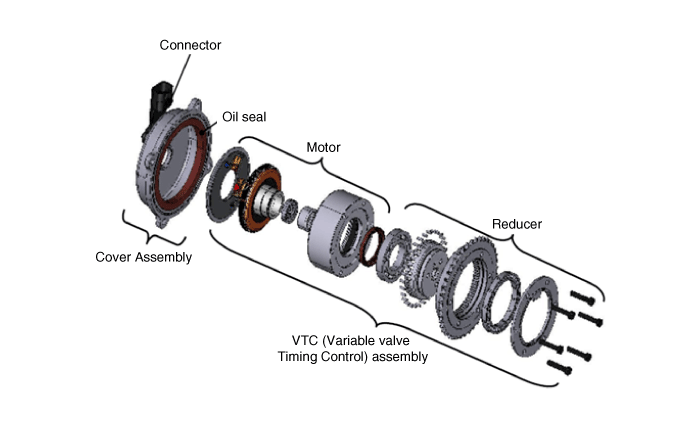
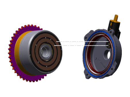
The appearance of the E-CVVT is similar to the hydraulic CVVT. The connector that controls the DC motor and the protective cover that protects the motor are installed on the upper part. The DC motor that drives the CVVT is installed inside, and the cover part is sealed so that oil does not enter inside.
Description and Operation
Description
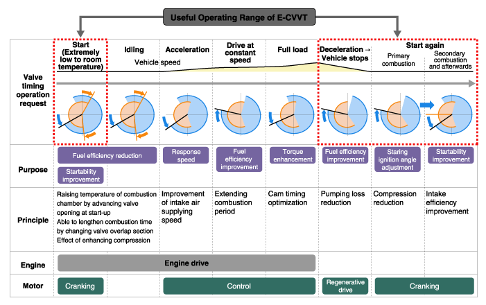
The E-CVVT (Electric Continuously Variable Valve Timing) system, located on the intake camshaft, uses engine rotation to control the camshaft angle relative to crankshaft rotation independently of engine oil pressure. Electronic control of the CVVT DC motor (duty signal) allows more precise system control compared with the previous hydraulic type. This increases the cam response speed to improve startability and reduce exhaust emissions. In addition, the operating range of the intake valve (valve opening angle) is expanded, improving output and fuel efficiency.
Operation
Circuit Diagrams
Wiring Diagram
Harness Connector
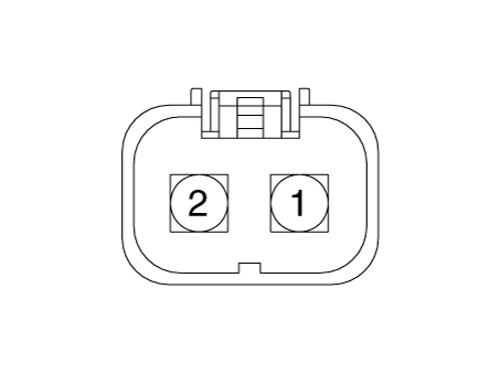
Repair Procedures
Removal
Remove the E-CVVT.
(Refer to Engine Mechanical System - "CVVT and Camshaft")
Installation
Install the E-CVVT.
(Refer to Engine Mechanical System - "CVVT and Camshaft")
Adjustment
Troubleshooting
Signal Waveform
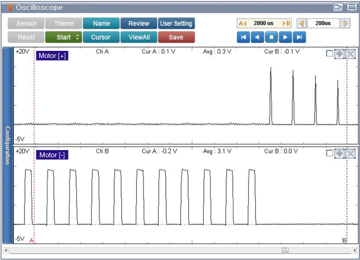
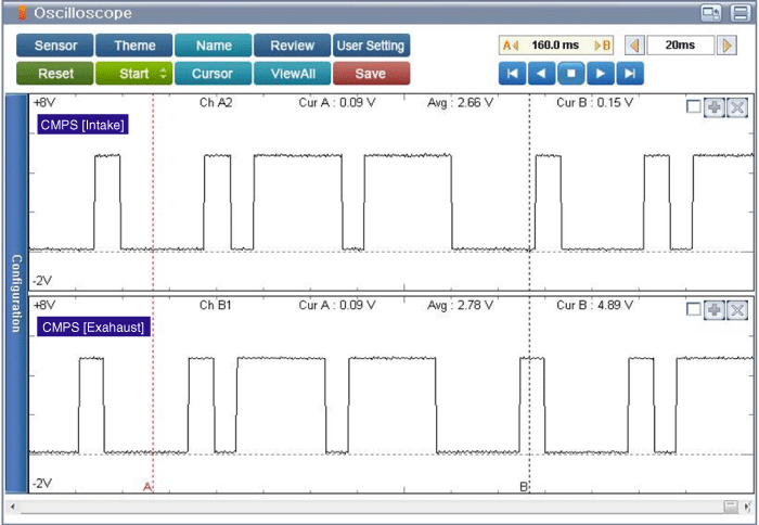
There is no separate sensor inside the E-CVVT. The valve timing is calculated by applying the 4-flange target wheel on the exhaust side and comparing the CKP and CMP signals.
Test yourself
A quick Kia Stinger CK quiz: every answer comes with an explanation and a link to the manual page.