Injector
Specifications
Specification
| Item | Specification |
| Coil Resistance (Ω) | 1,4–1,6 [20 °C] |
Description and Operation
Description
The GDI injector is similar to a standard injector, but it sprays fuel directly into the combustion chamber at a higher pressure and has a swirl disc to swirl the fuel at the injector outlet. This promotes fuel atomization.
The ECM controls both the power circuit (high side) that supplies voltage to the injectors and the ground circuit (low side) that supplies power to the injectors. Also, power is supplied to 2 injectors from one driver set. Since the ignition coils operate in pairs with cylinders (1-4 and 2-3), the injectors are also installed in pairs.

Circuit Diagrams
Wiring Diagram
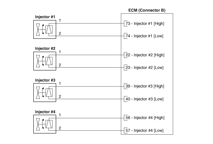
Harness Connector

Repair Procedures
Inspection
Turn the ignition off.
Disconnect the injector connector.
Measure the resistance between terminals 1 and 2 of the injector.
Make sure the resistance is within specification.
Specification: 1.18–1.31 [20 °C]
Removal
Release the residual pressure in the fuel line.
(See Fuel System - "Relieve Fuel Line Residual Pressure")
Turn the ignition switch OFF and disconnect the negative (-) battery terminal.
Remove the intake manifold.
(Refer to Engine Mechanical System - "Intake Manifold")
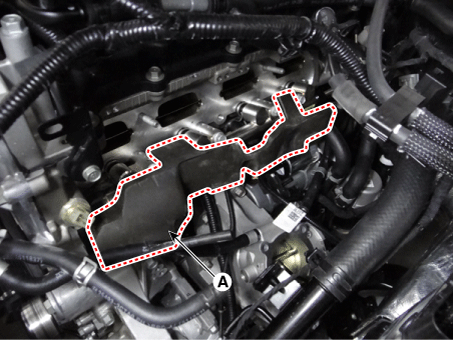
Remove the foam insulation on the delivery pipe (A).
Remove the hood upper cover assembly.
(Refer to Body (Interior and Exterior) - Hood Upper Cover.)
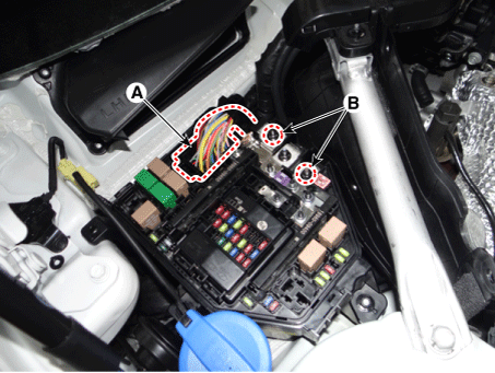
Remove the engine cover (A).

Disconnect the front control connector (A).
Remove the ground terminal nuts (B).
Remove the wiring protector (A).

Remove the high pressure fuel tube.
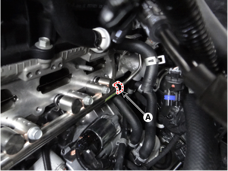
Remove the high-pressure fuel line mounting bolt (A).

Remove the high-pressure fuel line flange nut (A).

Remove the mounting bolts (A), then remove the delivery pipe and injector assembly from the engine.
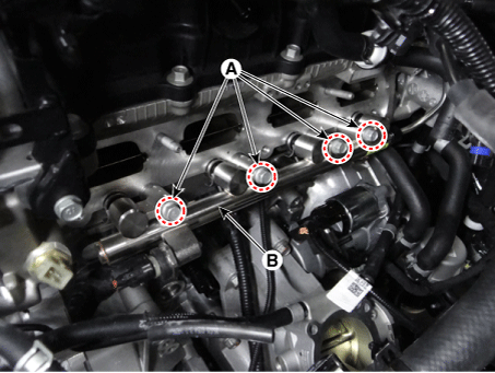
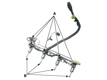
Disconnect the injector and the pressure sensor connector on the delivery pipe (A).
Remove the injector (B) from the delivery pipe.
Installation

Combustion Seal
Rubber Washer
Support Ring
O-ring
Install in the reverse order of removal.
Replacement
Replace the injector seal with a new one to prevent leakage after removing the injector.
Remove the combustion seal (A) using cutting pliers.

Before reinstalling the O-ring, clean the groove with a clean cloth.
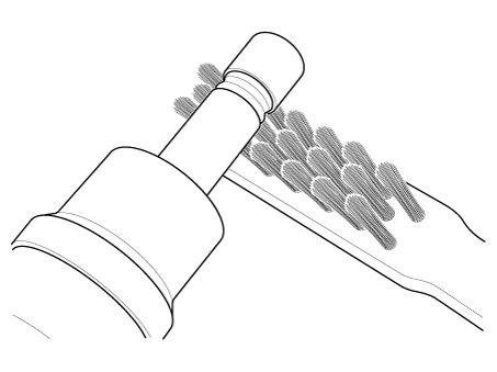
Thoroughly remove any carbon deposits on the injector sealing surface with a brass wire brush.
Place the O-ring installation guide (B) (SST No.: 09353-2B000) on the injector tip so as not to damage the injector tip (A).
Press the O-ring (C) with your thumb and index finger onto the tapered installation tool until it enters the groove.
The entire assembly should not take more than 2-3 seconds.


To determine the O-ring size, first insert the injector into the sizing tool (A) (SST No.: 09353-2B000), then press and simultaneously rotate it 180° in the gauging tool.

Remove the injector from the calibration tool by turning it in the direction opposite to the press-fit process.
Make sure the combustion chamber seal (A) is installed correctly.

Troubleshooting
Signal Waveform
The waveforms below are taken from injectors No. 1 and No. 4. The upper waveform is from the high-pressure side (supply side) of injectors No. 1 and No. 4. The middle waveform is from the low-pressure side (ground side) of injector No. 1, and the bottom waveform is from the low-pressure side of injector No. 4.
The middle waveform is the same as the upper one because there is no ground for the circuit. When there is no current flow in the circuit, injector No. 1 is not energized and fuel does not flow.
The bottom waveform shows that ground is supplied and there is a voltage drop across injector No. 4. When current flows in the circuit, injector No. 4 is open, energized, and fuel is flowing.

Test yourself
A quick Kia Stinger CK quiz: every answer comes with an explanation and a link to the manual page.