Heated Oxygen Sensor (HO2S)
Specifications
Specification
HO2S [Bank 1 / Sensor 1]
| Item | Specification |
| Heater Resistance (Ω) | 2,5–4,0 [20 °C] |
HO2S [Bank 1 / Sensor 2]
| Item | Specification |
| Heater Resistance (Ω) | 3,3–4,1 [20 °C] |
Description and Operation
Description
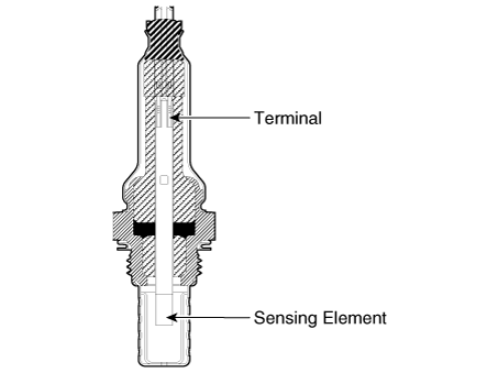
The Heated Oxygen Sensor (HO2S), consisting of zirconia and alumina, is installed both before and after the catalytic converter to detect the air-fuel ratio and send it to the ECM.
The sensor must be heated to operate properly. To heat it, the sensor has a heater that is controlled by the ECM using a duty cycle signal. When the exhaust gas temperature is below a specified value, the heater warms up the sensor tip.
Circuit Diagrams
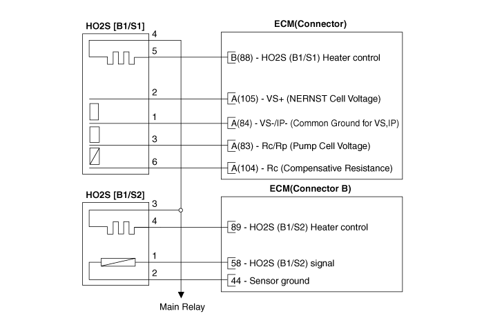
Wiring Diagram
Harness Connector
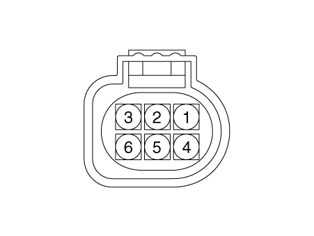
[Bank 1/Sensor 1]
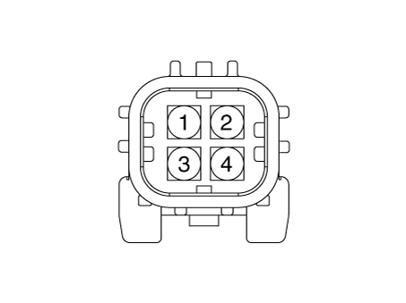
[Bank 1/Sensor 2]
Repair Procedures
Inspection
Turn the ignition off.
Disconnect the HO2S connector.
Measure the resistance between terminals 4 and 5 [B1/S1] of the HO2S.
Specification: 2.5 - 4.0 Ω [20 °C]
Measure the resistance between terminals 3 and 4 [B1/S2] of the HO2S.
Specification: 3.3 - 4.1 Ω [21 °C]
Make sure the resistance is within specification.
Removal
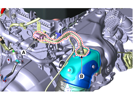
[Bank 1/Sensor 1]
Turn the ignition switch OFF and disconnect the negative (-) battery terminal.
Disconnect the connector (A) and remove the sensor (B).
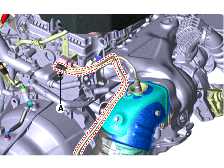
[Bank 1/Sensor 2]
Turn the ignition switch OFF and disconnect the negative (-) battery terminal.
Disconnect the connector (A).
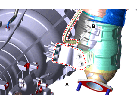
Raise the vehicle.
Remove the catalytic converter bracket (A).
Remove the sensor (B).
Installation
Install in the reverse order of removal.
Heated Oxygen Sensor:
39,2–49 N·m
Test yourself
A quick Kia Stinger CK quiz: every answer comes with an explanation and a link to the manual page.