Working with Electrical Circuit Diagrams
Electrical circuit diagrams are required to diagnose a fault or to install additional electrical equipment. The electrical circuit must be closed. For example, it is not sufficient for voltage to be applied to the positive terminal (+) of a headlamp while the other terminal (-) is not connected to ground.
For this reason, the battery ground cable (-) is connected to ground. In some cases this ground connection is not sufficient, and the corresponding consumer has a direct ground connection. The insulation of such a connection is usually brown. Individual circuits may include switches, relays, fuses, measuring instruments, electric motors and other electrical components. To connect these components correctly, the connecting cables have different colors and the contacts are numbered.
For ease of working with the vehicle electrical equipment, the entire system is divided into separate circuits. Electrical components that interact with each other are shown in a common diagram.
As a rule, positive contacts (+) are shown at the top of the diagram and ground contacts (-) at the bottom. Ground connections are usually made through the body or through an additional wire from a ground point on the body.
* Electrical components in the diagram are not shown to scale. For example, a 1 m cable is shown in the diagram only a few centimeters long.
Designations of important terminals:
Terminal 15. Powered from the ignition switch. Voltage is supplied only when the ignition is on. Cables are black or black with colored stripes.
Terminal 30. Battery voltage is constantly supplied to this terminal. Cables are usually red or red with stripes.
Terminal 31. Connected to ground. Ground wires are usually brown.
In electrical diagrams, all consumers and switches are shown in their initial (rest) position. Below, the current flow during switching is explained using the example of a two-stage switch.
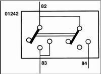
When the first stage of the switch is pressed, electric current flows from terminal 82 to terminal 83. The second-stage contact is in the middle position and makes no connection. Only when the second stage is pressed does the switch connect internal conductor 82 with conductor 84 and pass the electric current further.
In this case, the circuit from terminal 82 to terminal 83 remains closed through an internal branch in the switch.
The following example shows how to read an electrical diagram.
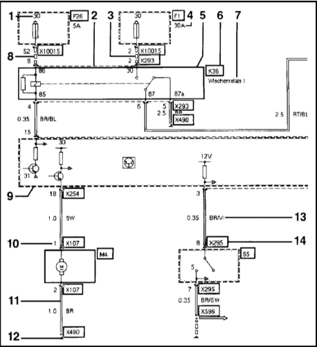
1) Terminal designation, here terminal 30.
2) The dashed line between pins 8 and 2 to connector X293 indicates that both pins belong to connector X293.
3) The dashed line from fuse F1 to pin 2 of connector X293 shows the positive wire from relay K36.
4) Fuse rated current, here: 30 A.
5) Switches and relays are always shown in their initial position. An element shown with a solid line is shown in full, here K36.
6) Component designation, here K36.
7) Component name, here wiper relay 1.
8) The dashed line from fuse F26 to pin 8 of connector X293 shows the positive control wire from relay K36.
9) An element shown with a dashed line is shown only partially, here: Base module A1.
10) Pin designation.
11) The double line from pin 2 of connector X107 to ground point X490 shows the ground wire to the washer pump motor M4.
12) Ground point X490.
13) Cable color, here: BR/V1 - brown/violet
14) Connector designation, here: X295.
Designations of the main components are as follows:
A - fuse holder/control unit/module
B - temperature sensor
E - lamps
F - fuse
H - horn/turn signal/stop lamp
K - relay
M - motor
N - radio receiver
R - potentiometer
S - switch
V - valve
X - connector or ground point
Y - outside mirror
Test yourself
A quick BMW 1 quiz: every answer comes with an explanation and a link to the manual page.