Single-Use Parts
Body Side Molding
In this manual: Single-Use Parts
37steps
~222min
4/5difficulty
Done 0 of 37
Contents:
Components and Components Location
Component
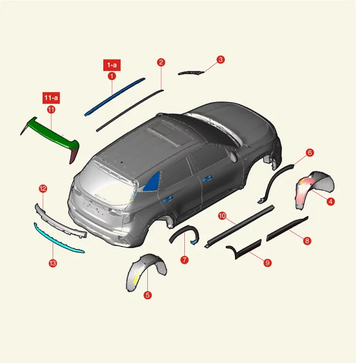
| 1. Roof Rack 1-a. 3,9 N·m 2. Roof Side Molding 3. A Pillar Garnish 4. Front Wheel Guard 5. Rear Wheel Guard 6. Fender Garnish 7. Quarter Garnish |
8. Front Door Garnish 9. Rear Door Garnish 10. Side Sill Molding 11. Rear Spoiler 11-a. 5,9 N·m 12. Inside Rear Combination Lamp 13. Tailgate Garnish Assembly |
Roof Side Molding Removal and Installation
Removal
- Remove the roof side molding (A).
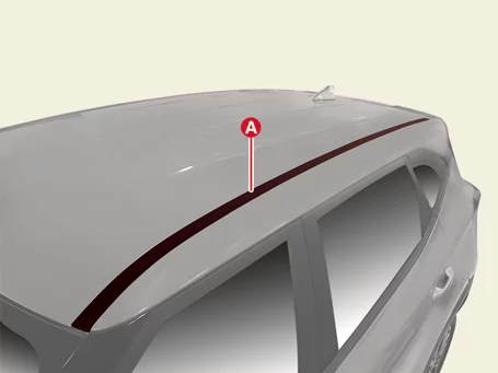
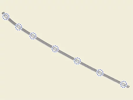
Clip position :

Installation
- Install in reverse order of removal.
Roof Rack Removal and Installation
Removal
- Remove the roof rack caps (A).
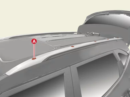
- Remove the roof rack (A) after removing the nuts.
Tightening torque : 3,9 N·m
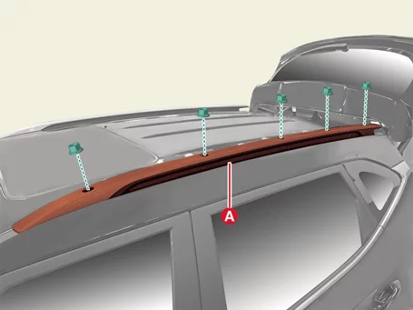
Installation
- Install in reverse order of removal.
Front Wheel Guard Removal and Installation
Removal
- Remove the front wheel and tires. (Refer to Suspension System - "Wheel")
- Remove the front wheel guard (A) after removing the clips and screws.
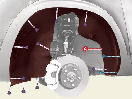
Installation
- Install in reverse order of removal.
Rear Wheel Guard Removal and Installation
Removal
- Remove the rear wheel and tires. (Refer to Suspension System - "Wheel")
- Remove the rear wheel guard (A) after removing the clips screws.
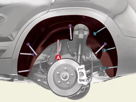
Installation
- Install in reverse order of removal.
Rear Spoiler Removal and Installation
Removal
- Remove the tailgate lid upper trim. (Refer to Tailgate - "Tailgate Lid Trim")
- Disconnect the rear spoiler connector (A).
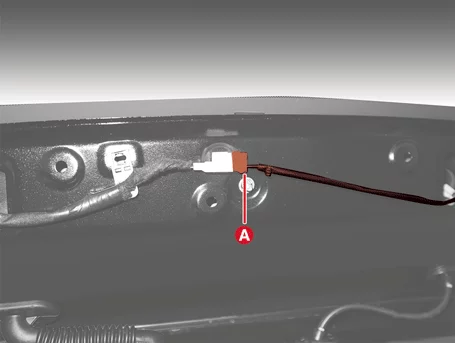
- Separate the rear washer nozzle (A).
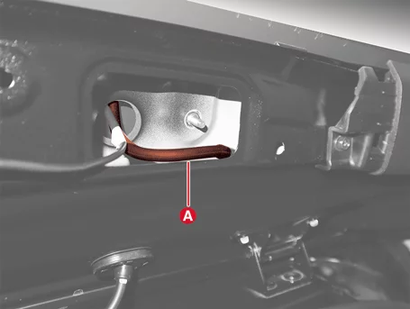
- Remove the rear spoiler hole plug (A).
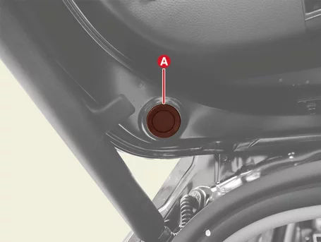
- Remove the rear spoiler nuts (A).
Tightening torque : 5,9 N·m
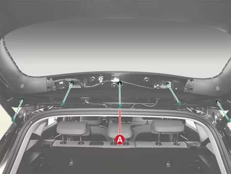
- Remove the rear spoiler (A).
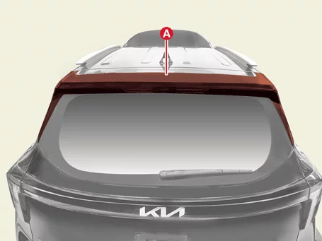
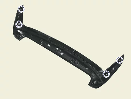
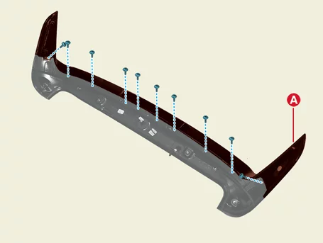
Clip position : - Remove the rear spoiler under cover (A) after removing the screws.
Installation
- Install in reverse order of removal.
Tailgate Garnish Removal and Installation
Removal
- Remove the inside rear combination lamp. (Refer to Body Electrical System - "Rear Combination Lamp")
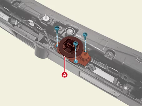
- Remove the connector bracket (A) after removing the screws.
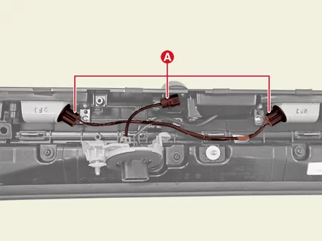
- Disconnect the license plate lamp and rear view camera connectors (A).
- Remove the tailgate lower garnish (A) after removing the screws.
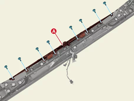

- Remove the tailgate garnish (A) after removing the screws.
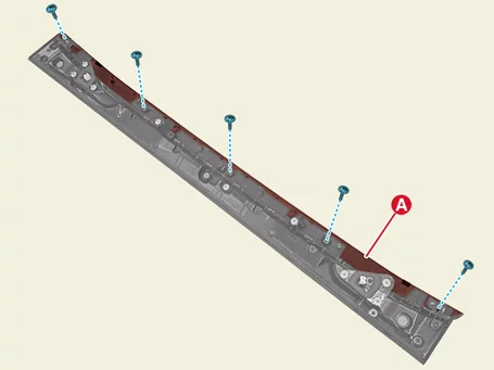
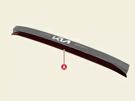
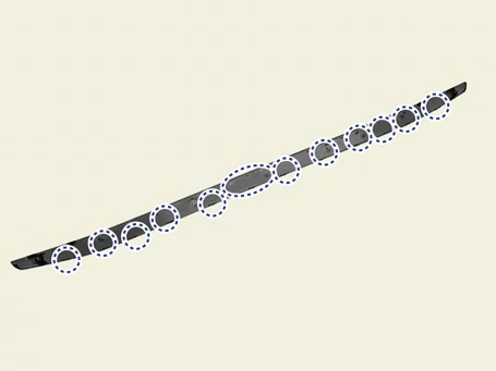
Clip position :
Installation
- Install in reverse order of removal.
Door Garnish Removal and Installation
Removal
Front Door Garnish- Remove the door garnish (A).
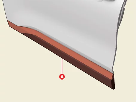

Clip position : - Remove the door garnish (A).
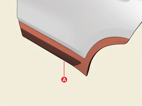
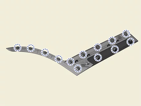
Clip position :
Installation
- Install in reverse order of removal.
Fender Garnish Removal and Installation
Removal
- Remove the front wheel guard. (Refer to Body Side Molding - "Front Wheel Guard")
- Remove the fender garnish (A).
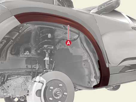
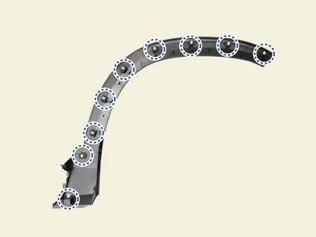
Clip position :
Installation
- Install in reverse order of removal.
Quarter Garnish Removal and Installation
Removal
- Remove the rear wheel guard. (Refer to Body Side Molding - "Rear Wheel Guard")
- Remove the quarter garnish (A).
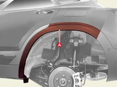
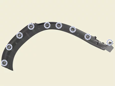
Clip position :
Installation
- Install in reverse order of removal.
A Pillar Garnish Removal and Installation
Removal
- Remove the A pillar garnish (A).

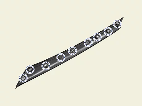
Clip position :
Installation
- Install in reverse order of removal.
Side Sill Molding Removal and Installation
Removal
- Remove the fender garnish. (Refer to Body Side Molding - "Fender Garnish")
- Remove the quarter garnish. (Refer to Body Side Molding - "Quarter Garnish")
- Remove the side sill molding (A)
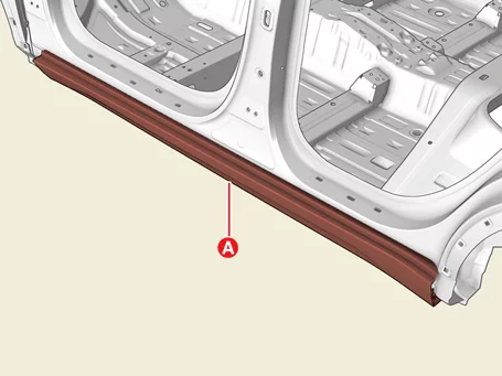
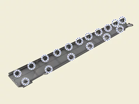
Clip position :
Installation
- Install in reverse order of removal.
Emblem Removal and Installation - Front
Emblem attached area
- Standard of measurement : From the top end of the radiator grille upper cover to the top of the emblem (vehicle center)
- Length (A) considering curved surface : 39 mm (1.5 in.)
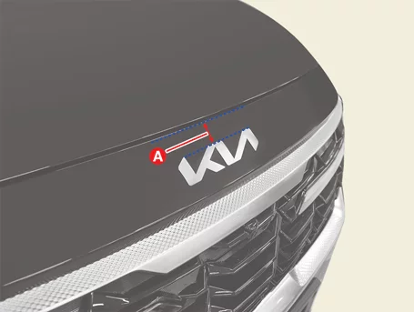
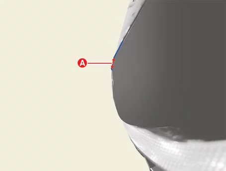
Removal
|
- Remove the emblem.
Installation
- Mark the center of the emblem.
Since the center of the emblem "I" is not located at the center of the vehicle, refer to the procedure below to mark the center.
- Mark the center (A) after measuring the horizontal length of the emblem
If the width is 21 cm (8.27 in.), the 11.5 cm (4.53 in.) part coincides with the center of the vehicle. As shown in the image below, the part that is skewed to the left of "I" is the center.
The shape of the emblem foam pad may be different for vehicles. - Mark the center of the emblem on the foam pad.
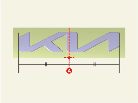
- Mark the center (A) after measuring the horizontal length of the emblem
- Measure the distance of the curved surface from the reference point and attach the emblem to the vehicle center.
B : Length of curved surface (C-D) 39 mm (1.5 in.) C : Radiator grill upper cover top end D : Middle end of the emblem
The attachment location is a value set based on the end of the emblem, not the end of the foam pad.
- Use a tool such as a roller to attach it closely to the vehicle body after attaching the emblem.
Note
- The following products can be utilized to accurately determine the location of the emblem attachment.
A. Self-adhesive measuring tape 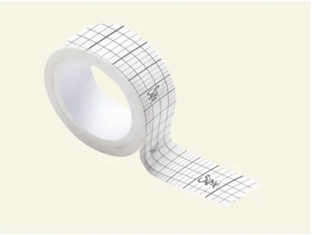
B. Attachable tape measure (Steel products may damage the vehicle) 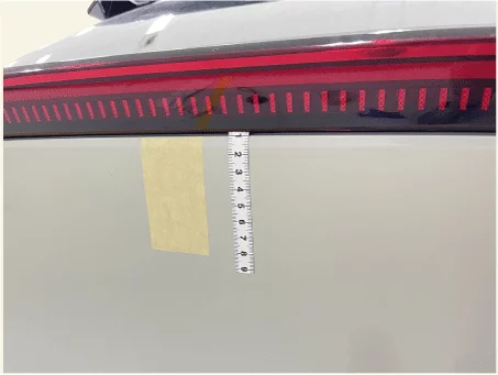
C. General masking tape 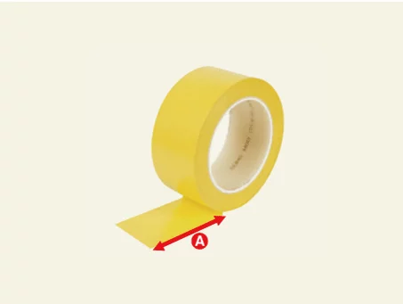
- The center of the vehicle is based on the end of radiator grille upper cover.

Emblem Removal and Installation - Rear
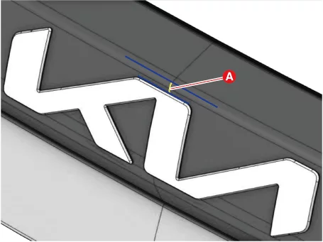
Emblem attached area
- Standard of measurement : from the top end of the rear combination lamp to the top of the emblem (vehicle center)
- Length considering curved surface : 5 mm (0.2 in.)
Removal
|
- Remove the emblem.
Installation
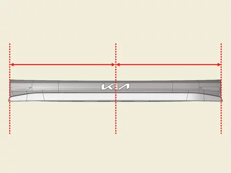
- Mark the center of the emblem.
Since the center of the emblem "I" is not located at the center of the vehicle, refer to the procedure below to mark the center.- Mark the center (A) after measuring the horizontal length of the emblem
If the width is 21 cm (8.27 in.), the 11.5 cm (4.53 in.) part coincides with the center of the vehicle. As shown in the image below, the part that is skewed to the left of "I" is the center.
The shape of the emblem foam pad may be different for vehicles. - Mark the center of the emblem on the foam pad.
- Mark the center (A) after measuring the horizontal length of the emblem
- Measure the distance of the curved surface from the reference point and attach the emblem to the vehicle center.
B : Length of curved surface (C-D) 5 mm (0.2 in.) C : Rear combination lamp top end D : Middle end of the emblem
The attachment location is a value set based on the end of the emblem, not the end of the foam pad.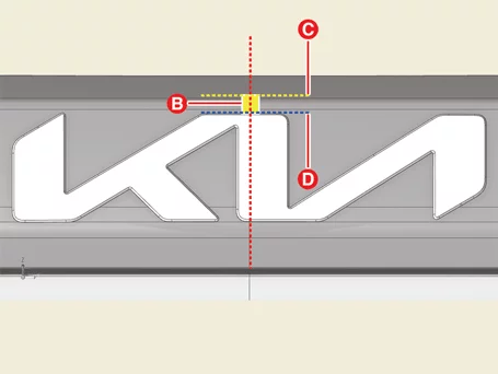
- Use a tool such as a roller to attach it closely to the vehicle body after attaching the emblem.
Note
- The following products can be utilized to accurately determine the location of the emblem attachment.
A. Self-adhesive measuring tape B. Attachable tape measure (Steel products may damage the vehicle) C. General masking tape - The center of the vehicle is based on the rear combination lamp end.
Was this page helpful?