Single-Use Parts
Crash Pad
In this manual: Single-Use Parts
60steps
~360min
4/5difficulty
Done 0 of 60
Contents:
Components and Components Location
Component

| 1. Crash Pad Side Cover 2. Crash Pad Lower Panel 3. Crash Pad Center Garnish 4. Steering Column Shroud Lower Panel 5. Crash Pad Garnish [Driver's side] 6. Center Speaker Grille 7. Head-Up Display (HUD) Unit Cover 8. Center Fascia Upper Panel |
9. Crash Pad Center Air Vent 10. Glove Box 11. Crash Pad Center Panel 11-a. 6-a. 6.9 - 10,8 N·m 12. Crash Pad Garnish [Driver's side] 13. Crash Pad Side Air Vent 14. Crash Pad Upper Garnish [Passenger's Side] 15. Main Crash Pad Assembly 15-a. 6.9 - 10,8 N·m 16. Cowl Crossbar Assembly 16-a. 22.6 - 30 N·m 16-b. 17.7 - 24 N·m 16-c. 16.7 - 23 N·m |
Crash Pad Side Cover Removal and Installation
Removal
- Remove the front door body side weatherstrip. (Refer to Front Door - "Front Door Weatherstrip")
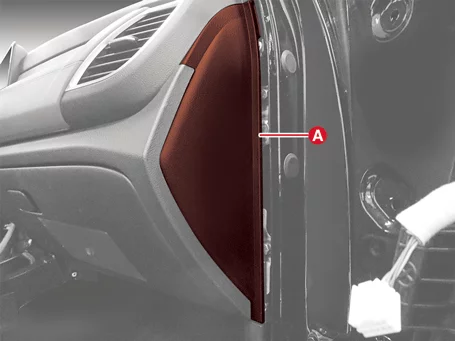
- Remove the crash pad side cover (A). [Driver's side]


[Passenger's side]
Clip position :

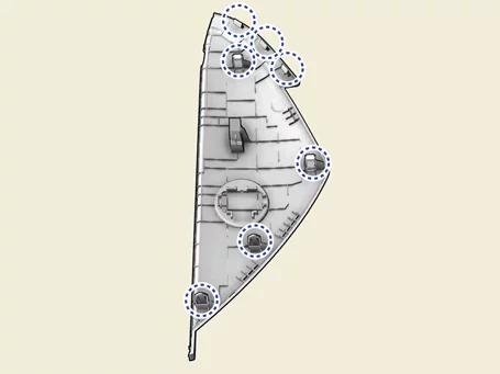
Clip position :
Installation
- Install in reverse order of removal.
Crash Pad Air Vent Removal and Installation
Removal
Center Air Vent- Remove the crash pad garnish [Passenger's side]. (Refer to Crash Pad - "Crash Pad Garnish")
- Remove the center air vent (A) after removing the screws.
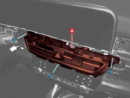

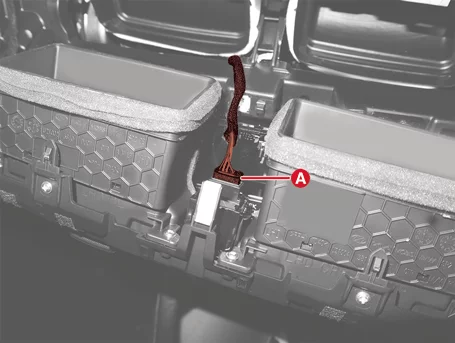
Clip position : - Disconnect the hazard switch connector (A).
- Remove the crash pad garnish [LH]. (Refer to Crash Pad - "Crash Pad Garnish")
- Remove the side air vent [Driver's side] (A).
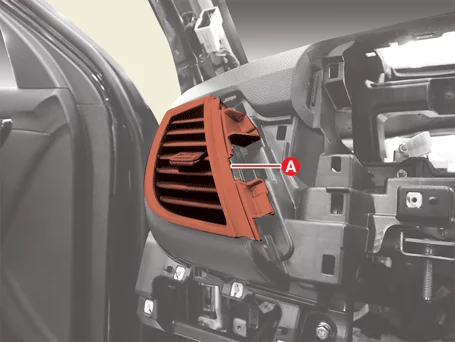
- Remove the crash pad garnish [Passenger's side]. (Refer to Crash Pad - "Crash Pad Garnish")
- Remove the side air vent [Passenger's side] (A) after removing the screw.
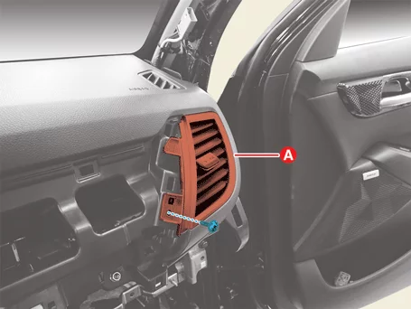
Installation
- Install in reverse order of removal.
Crash Pad Panel Removal and Installation
Removal
Crash Pad Lower Panel- Disconnect the battery negative ( - ) terminal.
- Remove the crash pad side cover [Driver's Side]. (Refer to Crash Pad - "Crash Pad Side Cover")
- Remove the crash pad lower panel (A) after removing the screws.
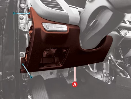
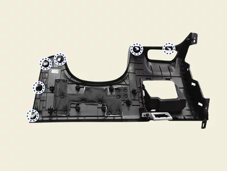
Clip position : - Disconnect the diagnostic tool connector (A).
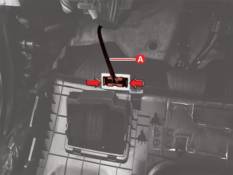
- Remove the crash pad lower panel.
- Remove the crash pad side cover [Passenger's side]. (Refer to Crash Pad - "Crash Pad Side Cover")
- Remove the glove box. (Refer to Crash Pad - "Glove Box")
- Remove the floor console assembly. (Refer to Floor Console - "Floor Console Assembly")
- Remove the heater and A/C control unit. (Refer to Heating,Ventilation And Air Conditioning - "Heater & A/C Control Unit (FATC)")
- Remove the crash pad center panel (A) after removing the screws and nuts.
Tightening torque : 6.9 - 10,8 N·m
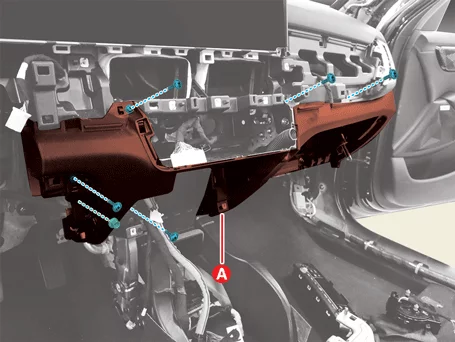
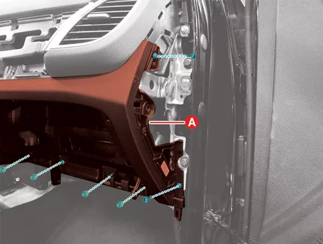
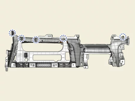
Clip position :
Installation
- Install in reverse order of removal.
Crash Pad Garnish Removal and Installation
Removal
Crash Pad Center Garnish- Remove the crash pad center garnish (A) by using the service hole (B).

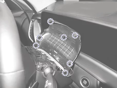
Clip position : - Remove the crash pad center garnish (A).
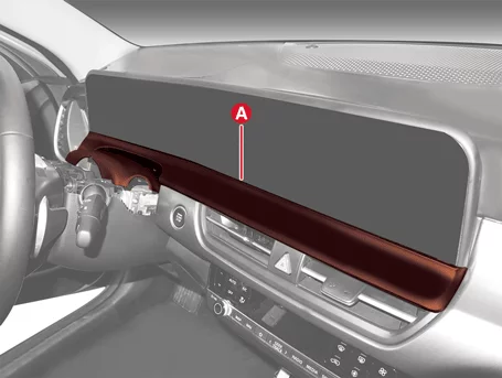

Clip position : - Remove the cluster. (Refer to Body Electrical System - "Cluster")
- Remove the crash pad lower panel. (Refer to Crash Pad - "Crash Pad Panel")
- Remove the crash pad garnish [Driver's side] (A).
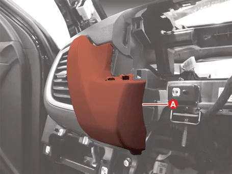
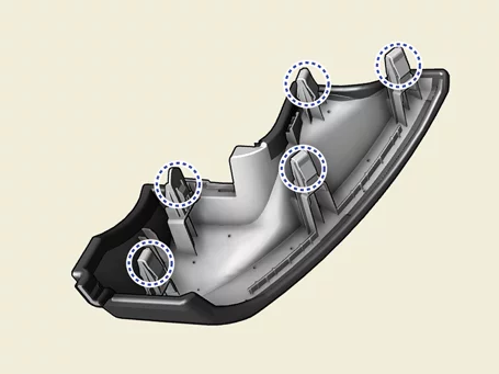
Clip position : - Remove the crash pad center garnish.
- Remove the crash pad garnish [Passenger's side] (A).
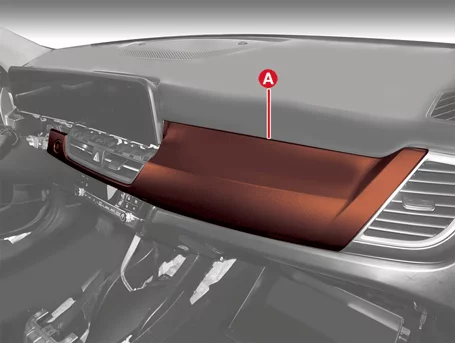
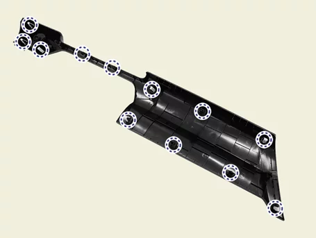
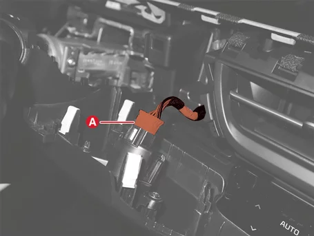
Clip position : - Disconnect the start and stop button connector (A).
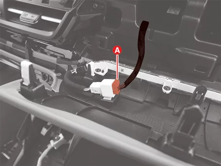
- Disconnect the mood lamp connector (A).
Installation
- Install in reverse order of removal.
Steering Column Shroud Panel Removal and Installation
Removal
- Remove the crash pad lower panel. (Refer to Crash Pad - "Crash Pad Lower Panel")
- Remove the crash pad center garnish (A) by using the service hole (B).
Clip position : - Turn the steering wheel left and right to remove the screws (A).
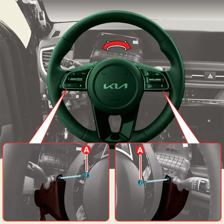
- Remove the steering column shroud panel (A) after removing the screw.
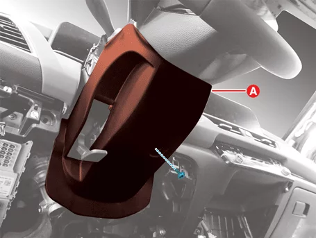
Installation
- Install in reverse order of removal.
Glove Box Removal and Installation
Removal
Glove Box- Open the glove box (A).
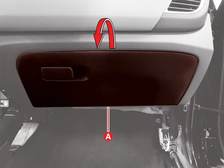
- Remove the air damper (A).
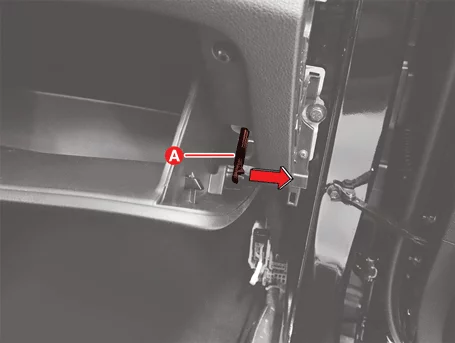
- Press the stopper in the direction of the arrow and lower the glove box (A).

- Remove the glove box (A) in the direction of the arrow.

Installation
- Install in reverse order of removal.
Main Crash Pad Assembly Removal and Installation
Removal
- Remove the front center speaker. (Refer to Body Electrical System - "Speaker")
- Remove the Head-Up Display (HUD) unit. (Refer to Body Electrical System - "Head-Up Display (HUD) Unit")
- Remove the crash pad antenna. (Refer to Body Electrical System - "Antenna")
- Remove the multi function switch. (Refer to Body Electrical System - "Multifunction Switch")
- Remove the crash pad center panel. (Refer to Crash Pad - "Crash Pad Panel")
- Remove the crash pad side air vent. (Refer to Crash Pad - "Crash Pad Air Vent")
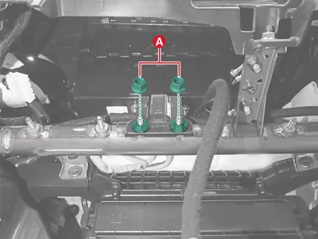
- Remove the Passenger Airbag (PAB) bracket nuts (A).
Tightening torque : 3.9 - 5,9 N·m (0.4 - 0.6 kgf·m, 2.9 - 4.3 lb·ft, 34.7 - 52.1 lb·in)
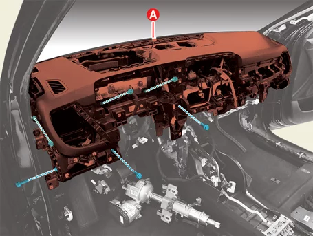
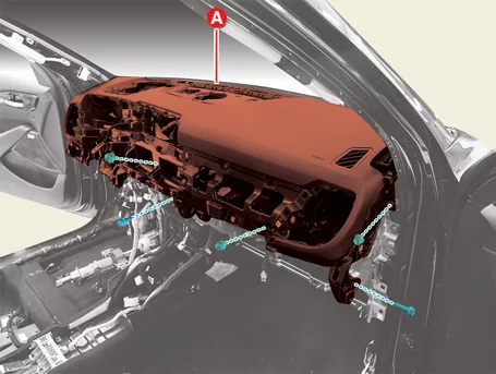
- Remove the main crash pad assembly (A) after removing the bolts and nuts.
Tightening torque : 6.9 - 10,8 N·m
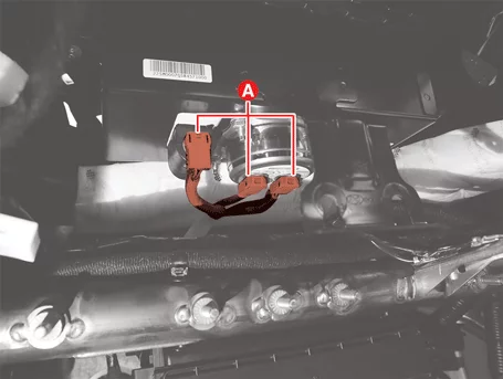
- Disconnect the Passenger Airbag (PAB) connectors (A).
Installation
- Install in reverse order of removal.
Cowl Cross Bar Assembly Removal and Installation
Removal
- Remove the front wiper motor. (Refer to Body Electrical System - "Wiper Motor")
- Remove the main crash pad assembly. (Refer to Crash Pad - "Main Crash Pad Assembly")
- Remove the Integrated Central control Unit (ICU). (Refer to Body Electrical System - "Integrated Central Control Unit (ICU)")
- Remove the Integrated Body Control Unit (IBU). (Refer to Body Electrical System - "Integrated Body Control Unit (IBU)")
- Remove interior antenna 1. (Refer to Body Electrical System - "Smart Key Antenna")
- Separate the MDPS column & housing. (Refer to Steering System - "MDPS Column & Housing")
- Disconnect the main wiring harness connector.
- Disconnect the airbag control module (SRSCM) connector (A).
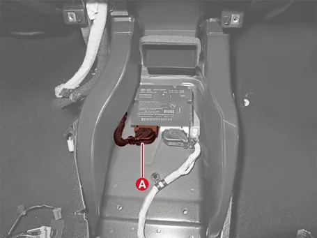
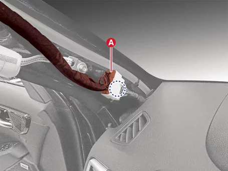
- Disconnect the roof antenna connector (A).

- Disconnect the roof trim connector (A).
- Disconnect the multi box connectors (A).
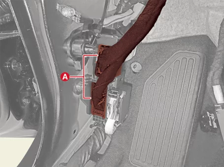
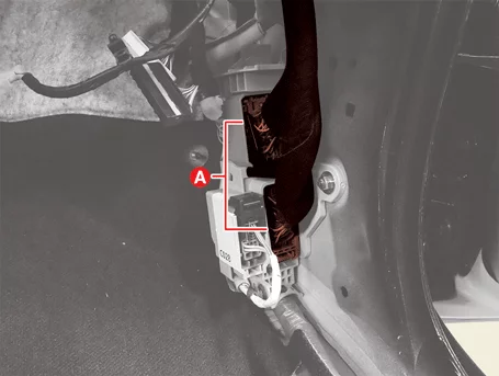
- Disconnect the airbag control module (SRSCM) connector (A).
- Disconnect the heater and blower unit connectors.
- Disconnect the temperature control actuator connector (A).

- Disconnect the mode control actuator connector (A).
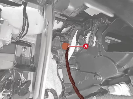
- Disconnect the auto defogging actuator connector (A).
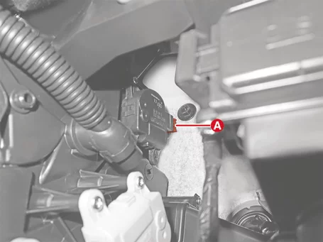
- Disconnect the evaporator sensor connector (A).
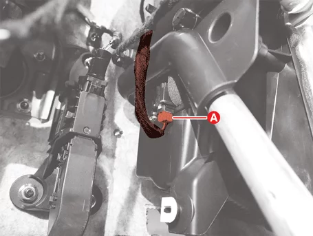
- Disconnect the blower motor connector (A).
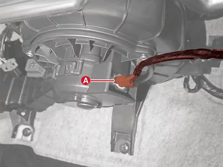
- Disconnect the intake actuator connector (A).
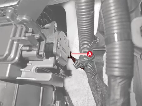
- Disconnect the blower resistor connector (A).
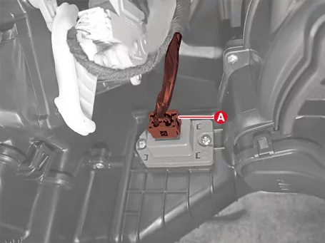
- Disconnect the temperature control actuator connector (A).
- Remove the main wiring harness wiring clip.
- Remove the A pillar wiring clips (A).
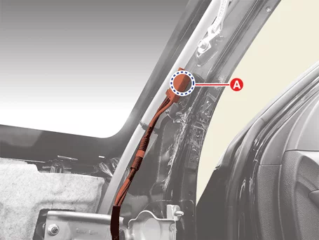
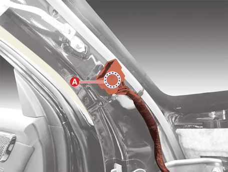
- Remove the heater and blower unit wiring clips (A).
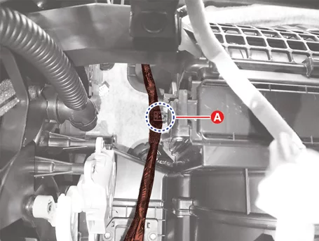
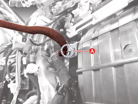
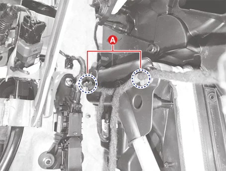
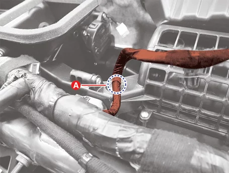
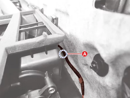
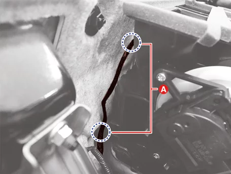
- Remove the A pillar wiring clips (A).
- Remove the driver's side shower duct (A) after removing the screw.
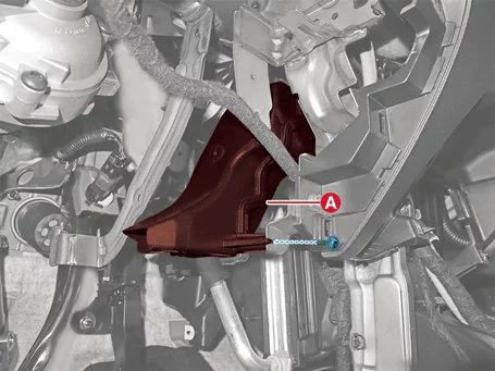
- Remove the dash panel cowl cross bar bolts (A).
Tightening torque : 22.6 - 30 N·m
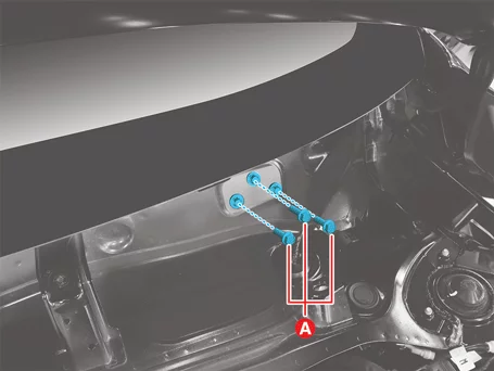
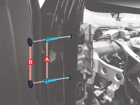
- Remove the side panel cowl cross bar bolts (A) after removing hole plug (B).
Tightening torque : 17.7 - 24 N·m
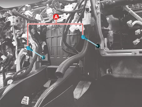
- Remove the heater and blower unit bolts (A).
Tightening torque : 3.9 - 5,9 N·m (0.4 - 0.6 kgf·m, 2.9 - 4.3 lb·ft, 34.7 - 52.1 lb·in)
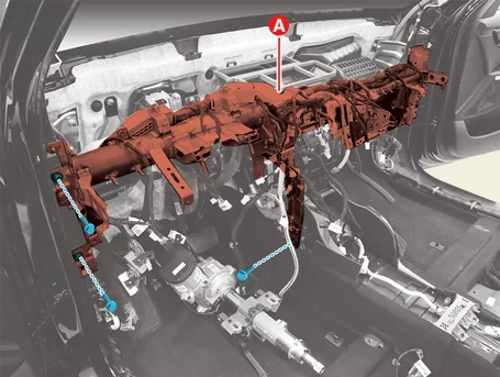
- Remove the cowl cross bar assembly (A) after removing the bolts.
Tightening torque Bolt : 6.9 - 26 N·m Nut : 3.9 - 5,9 N·m
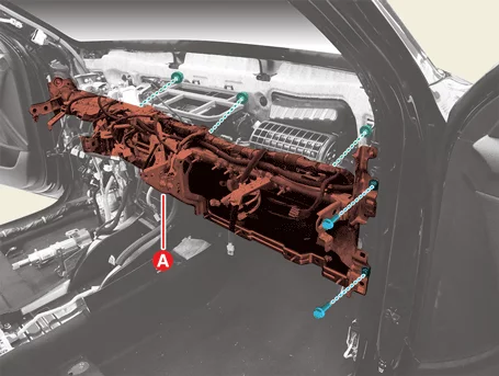
- Remove the main wiring harness (A).
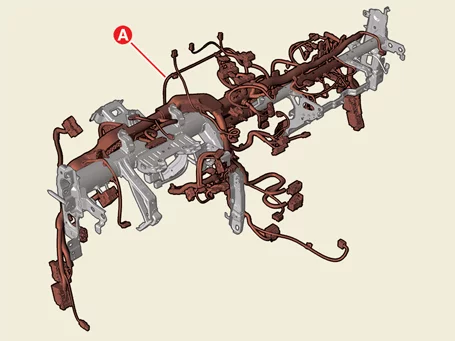
Installation
- Install in reverse order of removal.
Was this page helpful?