P17f1 Cvt Judder (c/v Inspection)
DTC DETECTION LOGIC
| DTC | CONSULT screen terms (Trouble diagnosis content) |
DTC detection condition | |
| P17F1 | CVT JUDDER (C/V INSPECTION) [CVT judder (Control Valve Inspection)] |
Diagnosis condition | — |
| Signal | — | ||
| Threshold | CVT hydraulic pressure variation detected. | ||
| Diagnosis delay time | — | ||
POSSIBLE CAUSE
Control valve assembly
FAIL-SAFE
Not changed from normal driving
CHECK DTC DETECTION AFTER DIAGNOSIS PROCEDURE
Turn ignition switch OFF and wait at least 10 seconds.
Turn ignition switch ON.
Perform test drive for 5 minutes or more.
Stop the Nissan Murano vehicle.
Check the DTC.
Is "judder" (shake, shudder, single or multiple bumps or viblation) occurred and is "P17F1" detected?
YES>>Go to Diagnosis Procedure.
NO>>INSPECTION END
CHECK DTC PRIORITY
When DTC P0776 is displayed together with P17F0, diagnose first the P17F0.
Is "P17F0" detected?
YES>>Perform diagnosis of P17F0. Refer to Diagnosis Procedure.
NO>>GO TO 2.
INSPECT CVT CHAIN
Inspect the CVT chain. Refer to Component Inspection.
Is CVT chain OK?
YES>>GO TO 3.
NO>>GO TO 4.
INSTALL NEW CONTROL VALVE
Install new control valve. Refer to Removal and Installation.
>>WORK END
REPLACE SUB-ASSEMBLY AND INSTALL NEW CONTROL VALVE
Replace sub-assembly and install new control valve. Refer to Disassembly & Assembly.
>>WORK END
CVT CHAIN BELT INSPECTION
Place the transmission gear selector in Neutral.
Leave the driver door unlatched.
Remove the control valve. Refer to Removal and Installation.
Secure the right front tire with a suitable strap
 . This will assist in making the chain belt turn.
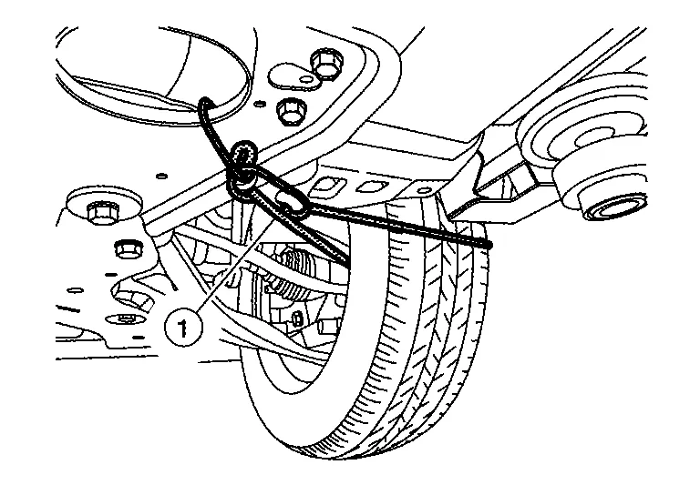
Mark the left front tire with a suitable marking. This will ensure all 360° of the chain belt is inspected.
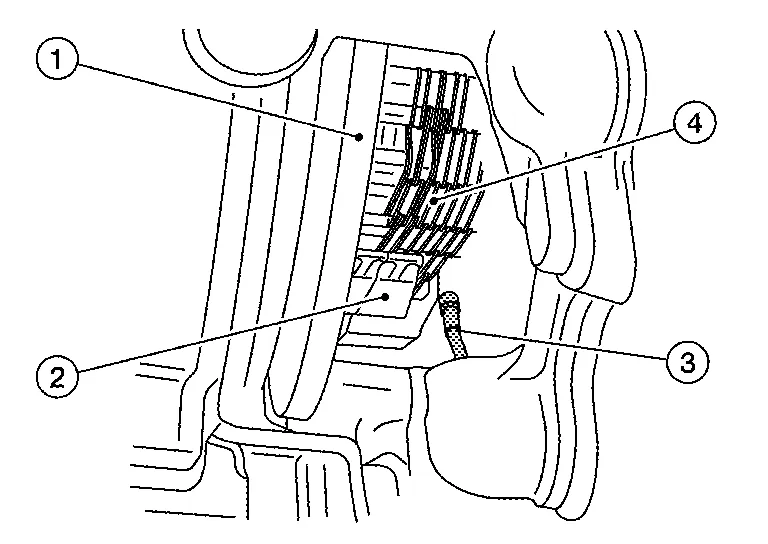
Using borescope J-51951 with mirror attachment, visually inspect the entirety of the two sides of the chain belt
that come in contact with the pulleys  . Slowly and carefully turn the left front tire one full turn in the forward rotation to view all of the chain belt.


Guide rail 
: Front Route the camera cable past the primary pulley and position the camera lens behind the plastic guide. See figure below.

Chain belt Camera cable Secondary pulley 
Plastic guide 
Primary pulley : Front First inspect the entire 360° of the driver side of the chain belt that comes in contact with the pulley. Refer to figures below for examples of normal and excessive wear patterns.
Pulley Guide rail Camera flexible tube Chain belt If the inspection result is OK on all 360° of the driver side, inspect all 360° of the passenger side of the chain belt. Refer to figures below for examples of normal and excessive wear patterns.

Chain belt Pulley Camera flexible tube Guide rail
CHAIN BELT WEAR PATTERNS
Examples of OK (normal) wear patterns.
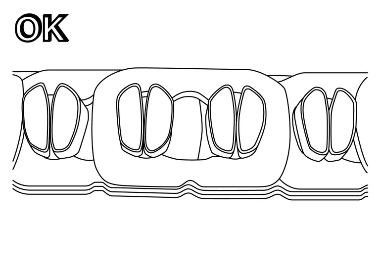
Chain contact surfaces appear smooth.
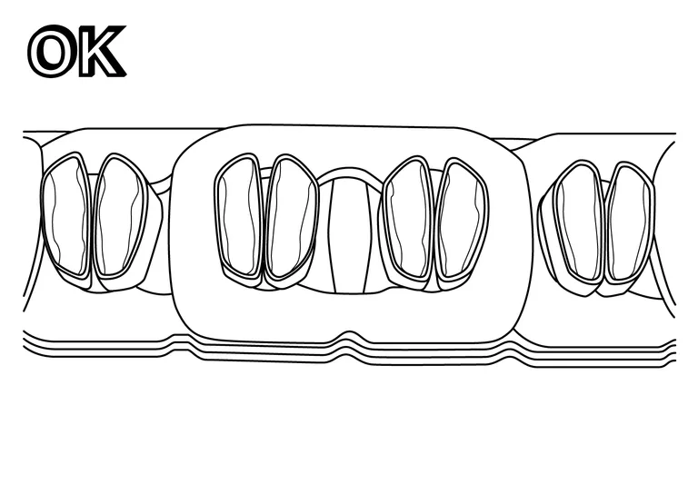
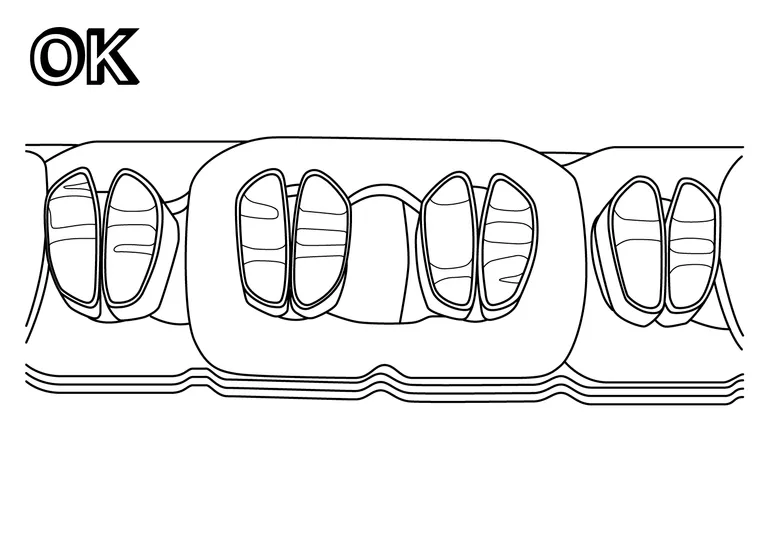
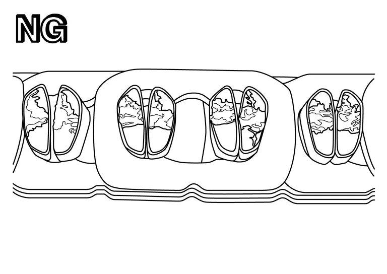
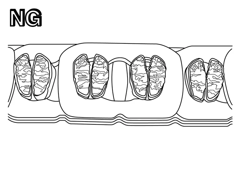
Examples of NG (abnormal) wear patterns.
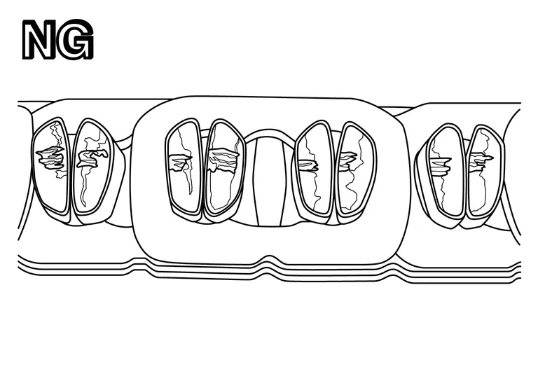
Chain contact surfaces show visible scuffing.