P2765 Input Speed Sensor B
DTC DETECTION LOGIC
| DTC | CONSULT screen terms (Trouble diagnosis content) |
DTC detection condition | |
| P2765 | INPUT SPEED SENSOR B (Input/Turbine Speed Sensor B Circuit) |
Diagnosis condition | When all of the following conditions are satisfied:
|
| Signal | — | ||
| Threshold | When all of the following conditions are satisfied:
|
||
| Diagnosis delay time | 5 seconds | ||
POSSIBLE CAUSE
Harness or connector (Output speed sensor circuit is open or shorted)
Output speed sensor
FAIL-SAFE
Start is slow
Acceleration is slow
Lock-up is not performed
Manual mode is not activated
PREPARATION BEFORE WORK
If another "DTC CONFIRMATION PROCEDURE" occurs just before, turn ignition switch OFF and wait for at least 10 seconds, then perform the next test.
>>GO TO 2.
CHECK DTC DETECTION
Start the engine.
Drive the Nissan Murano vehicle.
Maintain the following conditions for 10 seconds or more.
Selector lever : “D” position Engine speed : 1,200 rpm or more Nissan Murano Vehicle speed : 55 km/h or more Stop the vehicle.
Check the first trip DTC.
Is “P2765” detected?
YES>>Go to Diagnosis Procedure.
NO-1>>To check malfunction symptom before repair: Refer to Intermittent Incident.
NO-2>>Confirmation after repair: INSPECTION END
CHECK OUTPUT SPEED SENSOR POWER CIRCUIT
Turn ignition switch OFF.
Disconnect output speed sensor connector.
Turn ignition switch ON.
Check voltage between output speed sensor harness connector terminal and ground.
+ − Voltage Output speed sensor Connector Terminal F36 3 Ground 10 – 16 V
Is the inspection result normal?
YES>>GO TO 2.
NO>>GO TO 6.
CHECK OUTPUT SPEED SENSOR GROUND CIRCUIT
Check continuity between output speed sensor harness connector terminal and ground.
| Output speed sensor | — | Continuity | |
|---|---|---|---|
| Connector | Terminal | ||
| F36 | 1 | Ground | Existed |
Is the inspection result normal?
YES>>GO TO 3.
NO>>Repair or replace malfunctioning parts.
CHECK CIRCUIT BETWEEN OUTPUT SPEED SENSOR AND TCM (PART 1)
Turn ignition switch OFF.
Disconnect TCM connector.
Check continuity between output speed sensor harness connector terminal and TCM harness connector terminal.
Output speed sensor TCM Continuity Connector Terminal Connector Terminal F36 2 F25 34 Existed
Is the inspection result normal?
YES>>GO TO 4.
NO>>Repair or replace malfunctioning parts.
CHECK CIRCUIT BETWEEN OUTPUT SPEED SENSOR AND TCM (PART 2)
Check continuity between output speed sensor harness connector terminal and ground.
| Output speed sensor | — | Continuity | |
|---|---|---|---|
| Connector | Terminal | ||
| F36 | 2 | Ground | Not existed |
Is the inspection result normal?
YES>>GO TO 5.
NO>>Repair or replace malfunctioning parts.
CHECK TCM INPUT SIGNALS
Connect all of disconnected connectors.
Lift the Nissan Murano vehicle.
Start the engine.
Check frequency of output speed sensor.
+ − Condition Frequency
(Approx.)TCM Connector Terminal F25 34 Ground Selector lever: “M1” position
Nissan Murano Vehicle speed: 20 km/h
200 Hz
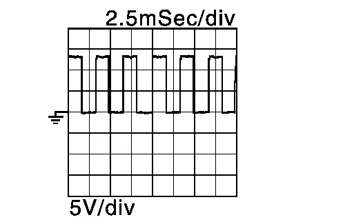
Is the inspection result normal?
YES>>Check intermittent incident. Refer to Intermittent Incident.
NO>>Replace output speed sensor. Refer to Removal and Installation.
DETECT MALFUNCTIONING ITEMS
Check the following items:
Harness open circuit or short circuit between ignition switch and IPDM E/R. Refer to Wiring Diagram - IGNITION POWER SUPPLY -.
Harness open circuit or short circuit between IPDM E/R connector terminal 61 and output speed sensor connector terminal 3.
10A fuse (No.43, located in the IPDM E/R). Refer to IPDM E/R Terminal Arrangement .
IPDM E/R
Is the check result normal?
YES>>Check intermittent incident. Refer to Intermittent Incident.
NO>>Repair or replace malfunctioning parts.