Illumination Circuit
DESCRIPTION
Power is supplied to the illumination of the radio receiver and display assembly and the steering pad switch assembly when the light control switch is in the TAIL or HEAD position.
WIRING DIAGRAM
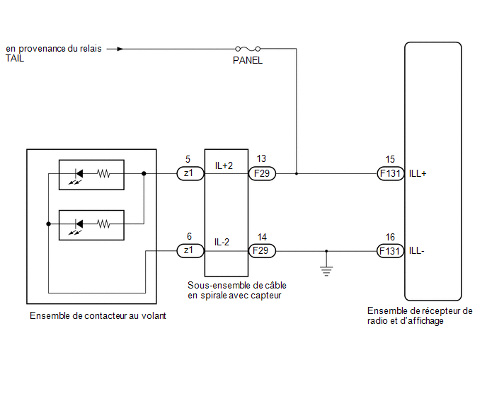
PRECAUTION / NOTICE / HINT
NOTICE:
- This vehicle is equipped with a Supplemental Restraint System (SRS) including components such as airbags. Before performing any service (including removal or installation of parts), carefully read the precautions for the Supplemental Restraint System.
Click here

- Check the fuses for the circuits related to this system before performing the following procedure.
PROCEDURE
CHECK ILLUMINATION
(a) Check whether the illumination of the radio receiver and display assembly, steering pad switch assembly, heater control switch or others (hazard switch, transmission control switch, etc.) lights up when the light control switch is set to the HEAD or TAIL position.
Result:
Result | Proceed to |
|---|---|
The illumination lights up for all components except the steering pad switch assembly. |
A |
All components light up except the radio receiver and display assembly. |
B |
No illumination (radio receiver and display assembly, hazard switch, heater control switch, etc.) lights up. |
C |
| B |  |
GO TO STEP 5 |
| C | |
GO TO ILLUMINATION SYSTEM |
|

CHECK WIRE HARNESS AND CONNECTOR (ILLUMINATION SIGNAL)
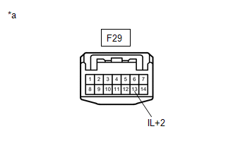
(a) Disconnect the connector from the spiral cable with sensor assembly.
(b) Measure the voltage according to the value(s) in the table below. Standard voltage:
|
|
| NG | |
REPAIR OR REPLACE HARNESS OR CONNECTOR |
|
CHECK STEERING PAD SWITCH ASSEMBLY
(a) Remove the steering pad switch assembly.
Click here
(b) Check the steering pad switch assembly.
Click here
(c) Make sure the steering pad switch assembly illumination lights up.
OK:
The steering pad switch assembly illumination lights up.
| NG | |
REPLACE STEERING PAD SWITCH ASSEMBLY |
|
CHECK SPIRAL CABLE WITH SENSOR SUB-ASSEMBLY
(a) Remove the spiral cable with sensor sub-assembly.
Click here
(b) Check the spiral cable with sensor sub-assembly.
Click here
NOTICE:
- Hold down the lock on the center section of the spiral cable with sensor sub-assembly to rotate the spiral cable with sensor sub-assembly.
- The spiral cable with sensor sub-assembly is a critical part of the SRS airbag system. Incorrect removal or installation of the spiral cable with sensor sub-assembly may prevent the airbag from deploying.
- If the spiral cable with sensor sub-assembly may break, do not rotate the spiral cable with sensor sub-assembly beyond the specified value.
| OK | |
REPAIR OR REPLACE WIRE HARNESS OR CONNECTOR (SPIRAL CABLE WITH SENSOR SUB-ASSEMBLY - RADIO RECEIVER AND DISPLAY ASSEMBLY OR BODY GROUND) |
| NG | |
REPLACE SPIRAL CABLE WITH SENSOR SUB-ASSEMBLY |
CHECK WIRE HARNESS AND CONNECTOR (ILLUMINATION SIGNAL)
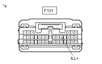
(a) Disconnect the radio receiver and display assembly connector.
(b) Measure the voltage according to the value(s) in the table below. Standard voltage:
|
|
| OK | |
REPLACE RADIO AND DISPLAY RECEIVER ASSEMBLY |
| NG | |
REPAIR OR REPLACE HARNESS OR CONNECTOR |