Parking Brake Switch Circuit
DESCRIPTION
This circuit connects the Skid Control ECU (Brake Actuator Assembly) to the radio and display receiver assembly.
WIRING DIAGRAM
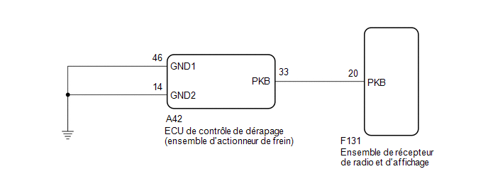
PROCEDURE
INSPECT ELECTRIC PARKING BRAKE SYSTEM
(a) Check the operation of the electric parking brake.
Click here
| NG |  |
GO TO ELECTRIC PARKING BRAKE SYSTEM |
|

INSPECT WIRE HARNESS AND CONNECTOR (SKID CONTROL ECU (BRAKE ACTUATOR ASSEMBLY) - RADIO AND DISPLAY RECEIVER ASSEMBLY)
(a) Disconnect the F131 connector from the radio and display receiver assembly.
(b) Disconnect the A42 connector from the Skid Control ECU (Brake Actuator Assembly).
(c) Measure the resistance according to the value(s) in the table below.
Standard resistance:
Tester Connection | Condition | Specified Condition |
|---|---|---|
F131-20 (PKB) - A42-33 (PKB) |
Always |
Below 1 Ω |
F131-20 (PKB) - Body ground |
Always |
10 kΩ minimum |
| OK | |
GO TO APPLICABLE SYSTEM AS INDICATED IN THE PROBLEM SYMPTOMS TABLE |
| NG | |
REPAIR OR REPLACE HARNESS OR CONNECTOR |