Satellite radio broadcasts cannot be received
PRECAUTION / NOTICE / HINT
NOTICE:
Some satellite radio broadcasts require payment. A contract must be established between a satellite radio company and the user. If the contract expires, it will no longer be possible to listen to the broadcast.
WIRING DIAGRAM
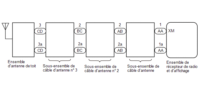
TMMT manufactured
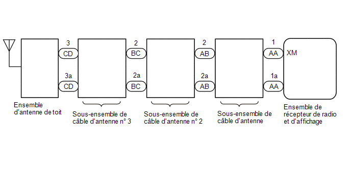
TMC manufactured
PROCEDURE
CHECK SURROUNDINGS
(a) Check whether the vehicle is in an area of poor reception due to an obstruction above the vehicle.
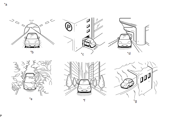
*a |
Example |
*b |
In a tunnel |
*c |
In a building |
*d |
Under an overpass |
*e |
In a forest or on a tree-lined road |
*f |
Between tall buildings |
*g |
Under a cliff or overhang |
- |
- |
HINT:
If there is an obstruction above the vehicle, for example, if the vehicle is in a building or under a tunnel, reception may not be possible.
OK:
No obstruction above the vehicle
| NG |  |
END (MOVE VEHICLE TO A LOCATION WITH BETTER RECEPTION) |
|

CHECK RADIO AND DISPLAY SYSTEM
(a) Check whether CH001 (free broadcast) can be received.
OK:
CH001 can be received.
| NG | |
GO TO STEP 6 |
|
CHECK DISPLAY SETTING
(a) Check the display screen.
Result:
Result | Proceed to |
|---|---|
"SAT Ch Unauth" is displayed. |
A |
"-----" is displayed. |
B |
None of the above messages is displayed. |
C |
| B | |
NO SONG/PROGRAM TITLE OR ARTIST/FEATURE NAME IS ASSOCIATED WITH THE CHANNEL AT THIS TIME |
| C | |
GO TO STEP 6 |
|
CHECK CONTRACT CONDITIONS
(a) Check whether the paid subscription has been renewed or has expired.
OK:
The paid subscription is valid.
| NG | |
TO RECEIVE PAID BROADCASTS, A CONTRACT MUST BE CONCLUDED WITH A SATELLITE RADIO COMPANY |
|
UPDATE ACTIVATION
(a) Update the activation by referring to the satellite radio company website (http://www.siriusxm.com).
OK:
The malfunction disappears.
HINT:
The SiriusXM Radio ID required to update the activation is displayed when CH000 is selected on the satellite radio.
| OK | |
END |
| NG | |
GO TO APPLICABLE SYSTEM AS INDICATED IN THE PROBLEM SYMPTOMS TABLE |
CHECK DISPLAY
(a) Check the display screen.
Result:
Result | Proceed to |
|---|---|
"SAT Ck Antenna" is displayed. |
A |
"SAT No Signal" is displayed. |
B |
"Loading" is displayed. |
|
"SAT Ch Off Air" is displayed. |
C |
Once "SAT Ch Unavail" is displayed, the screen automatically switches to CH001. |
D |
None of the above messages is displayed. |
E |
| B | |
END (MOVE VEHICLE TO A LOCATION WITH BETTER RECEPTION) |
| C | |
THE CHANNEL IS NOT TRANSMITTING AT THE MOMENT. THE BROADCAST CAN BE HEARD OR VIEWED WHEN IT IS BROADCAST AGAIN. (CHECK WITH THE RADIO STATION) |
| D | |
THE BROADCAST HAS ENDED (CHECK WITH THE RADIO STATION) |
| E | |
GO TO STEP 14 |
|
CHECK THE ANTENNA CABLE SUB-ASSEMBLY
(a) Replace the antenna cable sub-assembly with a new or normally functioning one, and check whether radio signals can be received normally.
Click here
OK:
Radio signals are received normally.
Result:
Result | Proceed to |
|---|---|
OK |
A |
NG (for TMMT manufactured) |
B |
NG (for TMC manufactured) |
C |
| A | |
END |
| C | |
GO TO STEP 11 |
|
CHECK ANTENNA CABLE SUB-ASSEMBLY NO. 2
(a) Disconnect the antenna cable sub-assembly No. 2 connector from the antenna cable sub-assembly. |
|
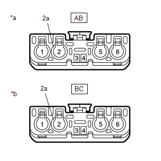
(b) Disconnect the antenna cable sub-assembly No. 2 connector from the antenna cable sub-assembly No. 3.
(c) Measure the resistance according to the value(s) in the table below.
Standard resistance:
Tester Connection | Condition | Specified Condition |
|---|---|---|
AB-2 - BC-2 |
Always |
Below 1 Ω |
AB-2a - BC-2a |
Always |
Below 1 Ω |
AB-2 - Body Ground |
Always |
10 kΩ minimum |
AB-2a - Body Ground |
Always |
10 kΩ minimum |
| NG | |
REPLACE NO. 2 ANTENNA CABLE SUB-ASSEMBLY |
|
INSPECT ANTENNA CABLE ASSY NO. 3
(a) Disconnect the No. 3 antenna cable assy connector from the No. 2 antenna cable assy. |
|
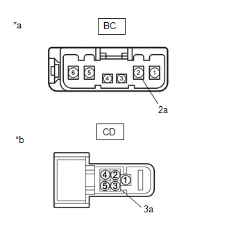
(b) Disconnect the No. 3 antenna cable assy connector from the roof antenna assy.
(c) Measure the resistance according to the value(s) in the table below.
Standard resistance:
Tester Connection | Condition | Specified Condition |
|---|---|---|
BC-2 - CD-3 |
Always |
Below 1 Ω |
BC-2a - CD-3a |
Always |
Below 1 Ω |
BC-2 - Body Ground |
Always |
10 kΩ minimum |
BC-2a - Body Ground |
Always |
10 kΩ minimum |
| NG | |
REPLACE NO. 3 ANTENNA CABLE SUB-ASSEMBLY |
|
REPLACE ROOF ANTENNA ASSY
(a) Replace the roof antenna assembly with a new or normally functioning one, and check whether radio signals can be received normally.
Click here
OK:
Radio signals are received normally.
| OK | |
END |
| NG | |
GO TO APPLICABLE SYSTEM AS INDICATED IN THE PROBLEM SYMPTOMS TABLE |
CHECK ANTENNA CABLE SUB-ASSEMBLY NO. 2
(a) Disconnect the antenna cable sub-assembly No. 2 connector from the antenna cable sub-assembly. |
|
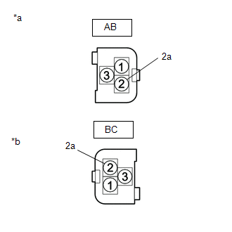
(b) Disconnect the antenna cable sub-assembly No. 2 connector from the antenna cable sub-assembly No. 3.
(c) Measure the resistance according to the value(s) in the table below.
Standard resistance:
Tester Connection | Condition | Specified Condition |
|---|---|---|
AB-3 - BC-2 |
Always |
Below 1 Ω |
AB-3a - BC-2a |
Always |
Below 1 Ω |
AB-3 - Body ground |
Always |
10 kΩ minimum |
AB-3a - Body ground |
Always |
10 kΩ minimum |
| NG | |
REPLACE NO. 2 ANTENNA CABLE SUB-ASSEMBLY |
|
INSPECT ANTENNA CABLE ASSY NO. 3
(a) Disconnect the No. 3 antenna cable assy connector from the No. 2 antenna cable assy. |
|
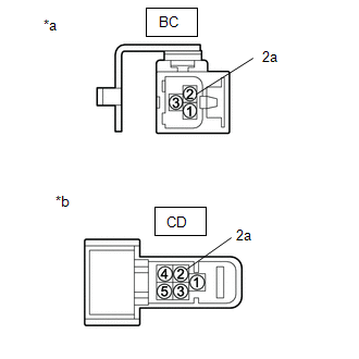
(b) Disconnect the No. 3 antenna cable assy connector from the roof antenna assy.
(c) Measure the resistance according to the value(s) in the table below.
Standard resistance:
Tester Connection | Condition | Specified Condition |
|---|---|---|
BC-2 - CD-2 |
Always |
Below 1 Ω |
BC-2a - CD-2a |
Always |
Below 1 Ω |
BC-2 - Body Ground |
Always |
10 kΩ minimum |
BC-2a - Body Ground |
Always |
10 kΩ minimum |
| NG | |
REPLACE NO. 3 ANTENNA CABLE SUB-ASSEMBLY |
|
REPLACE ROOF ANTENNA ASSY
(a) Replace the telephone antenna assembly with a new or normally functioning one, and check whether radio signals can be received normally.
Click here
OK:
Radio signals are received normally.
| OK | |
END |
| NG | |
GO TO APPLICABLE SYSTEM AS INDICATED IN THE PROBLEM SYMPTOMS TABLE |
CHECK THE CURRENTLY SELECTED CHANNEL
(a) Check whether CH000 is currently selected.
OK:
CH000 is selected.
| OK | |
END (CH000 DOES NOT TRANSMIT ANY SOUND. SELECT ANOTHER CHANNEL.) |
| NG | |
GO TO APPLICABLE SYSTEM AS INDICATED IN THE PROBLEM SYMPTOMS TABLE |