Speaker Circuit
DESCRIPTION
If there is a short circuit in a speaker circuit, the radio and display receiver assembly detects it and stops outputting to the speakers.
As a result, no sound comes from the speakers, even if there is no malfunction in the radio and display receiver assembly, the DCM (Telematics Transceiver)*1 or the speakers.
- *: with manual (SOS) switch
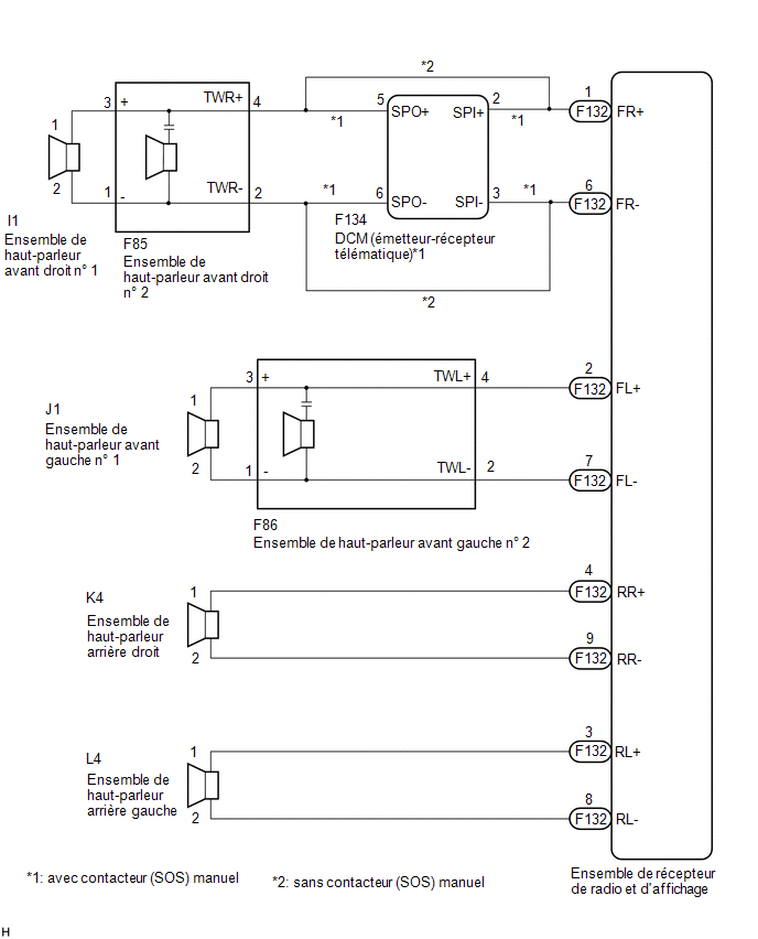
WIRING DIAGRAM
PRECAUTION / NOTICE / HINT
NOTICE:
If the DCM (Data Communication Module) has been replaced, perform the activation procedure using the DCM screen (with SOS (manual)).
Click here
PROCEDURE
INSPECT SPEAKER (OPERATION CHECK)
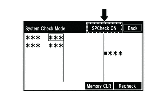
(a) Select the "System Check Mode" screen. Refer to Speaker Check in the Operation Check. Click here |
 |
(b) Perform the operation check described above and identify the speaker that does not operate.
Result:
Speaker does not operate | Proceed to |
|---|---|
Front Speaker Assembly No. 1 or Front Speaker Assembly No. 2 (with SOS (Manual) Switch) |
A |
Front Speaker Assembly No. 1 or Front Speaker Assembly No. 2 (Manual (without SOS) Switch) |
B |
Rear Speaker Assembly |
C |
HINT:
If no sound can be heard from the speakers, inspect all of them.
| B |  |
GO TO STEP 7 |
| C | |
GO TO STEP 10 |
|

INSPECT WIRE HARNESS AND CONNECTOR (RADIO AND DISPLAY RECEIVER ASSEMBLY - DCM (TELEMATICS TRANSCEIVER) AND FRONT SPEAKER ASSEMBLY NO. 2)
(a) Disconnect the F132 radio and display receiver assembly connector.
(b) Disconnect the F134 DCM (telematics transceiver) connector.
(c) Disconnect the F85 and F86 connectors from the Front Speaker Assembly No. 2.
(d) Measure the resistance according to the value(s) in the table below.
Standard resistance:
Tester Connection | Condition | Specified Condition |
|---|---|---|
F132-1 (FR+) - F134-2 (SPI+) |
Always |
Below 1 Ω |
F132-6 (FR-) - F134-3 (SPI-) |
Always |
Below 1 Ω |
F134-5 (SPO+) - F85-4 (TWR+) |
Always |
Below 1 Ω |
F134-6 (SPO-) - F85-2 (TWR-) |
Always |
Below 1 Ω |
F132-2 (FL+) - F86-4 (TWL+) |
Always |
Below 1 Ω |
F132-7 (FL-) - F86-2 (TWL-) |
Always |
Below 1 Ω |
F132-1 (FR+) or F134-2 (SPI+) - Body ground |
Always |
10 kΩ minimum |
F132-6 (FR-) or F134-3 (SPI-) - Body ground |
Always |
10 kΩ minimum |
F134-5 (SPO+) or F85-4 (TWR+) - Body ground |
Always |
10 kΩ minimum |
F134-6 (SPO-) or F85-2 (TWR-) - Body ground |
Always |
10 kΩ minimum |
F132-2 (FL+) or F86-4 (TWL+) - Body ground |
Always |
10 kΩ minimum |
F132-7 (FL-) or F86-2 (TWL-) - Body ground |
Always |
10 kΩ minimum |
| NG | |
REPAIR OR REPLACE HARNESS OR CONNECTOR |
|
INSPECT WIRE HARNESS AND CONNECTOR (FRONT SPEAKER ASSEMBLY NO. 1 - FRONT SPEAKER ASSEMBLY NO. 2)
(a) Disconnect connectors I1 and J1 from the No. 1 front speaker assembly.
(b) Disconnect connectors F85 and F86 from the No. 2 front speaker assembly.
(c) Measure the resistance according to the value(s) in the table below.
Standard resistance:
Tester Connection | Condition | Specified Condition |
|---|---|---|
I1-1 - F85-3 (+) |
Always |
Below 1 Ω |
I1-2 - F85-1 (-) |
Always |
Below 1 Ω |
J1-1 - F86-3 (+) |
Always |
Below 1 Ω |
J1-2 - F86-1 (-) |
Always |
Below 1 Ω |
I1-1 or F85-3 (+) - Body ground |
Always |
10 kΩ minimum |
I1-2 or F85-1 (-) - Body ground |
Always |
10 kΩ minimum |
J1-1 or F86-3 (+) - Body ground |
Always |
10 kΩ minimum |
J1-2 or F86-1 (-) - Body ground |
Always |
10 kΩ minimum |
| NG | |
REPAIR OR REPLACE HARNESS OR CONNECTOR |
|
CHECK DCM (TELEMATICS TRANSCEIVER)
(a) Disconnect the DCM (telematics transceiver).
Click here
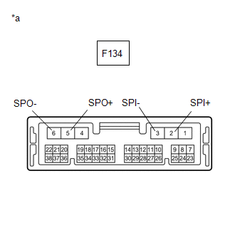
(b) Measure the resistance according to the value(s) in the table below. Standard resistance:
|
|
| NG | |
REPLACE DCM (DATA COMMUNICATION MODULE) |
|
INSPECT NO. 2 FRONT SPEAKER ASSEMBLY
(a) Remove the No. 2 front speaker assembly.
Click here
(b) Inspect the No. 2 front speaker assembly.
Click here
(c) Make sure the malfunction disappears when a new or normal Front Speaker Assembly No. 2 is installed.
OK:
The malfunction disappears.
| OK | |
END |
|
INSPECT NO. 1 FRONT SPEAKER ASSEMBLY
(a) Remove the No. 1 front speaker assembly.
Click here
(b) Inspect the No. 1 front speaker assembly.
Click here
| OK | |
GO TO APPLICABLE SYSTEM AS INDICATED IN THE PROBLEM SYMPTOMS TABLE |
| NG | |
REPLACE NO. 1 FRONT SPEAKER ASSEMBLY |
INSPECT WIRE HARNESS AND CONNECTOR (RADIO AND DISPLAY RECEIVER ASSEMBLY - FRONT SPEAKER ASSEMBLY NO. 1 AND FRONT SPEAKER ASSEMBLY NO. 2)
(a) Disconnect the F132 radio and display receiver assembly connector.
(b) Disconnect the I1 and J1 connectors from the Front Speaker Assembly No. 1.
(c) Disconnect the F85 and F86 connectors from the Front Speaker Assembly No. 2.
(d) Measure the resistance according to the value(s) in the table below.
Standard resistance:
Tester Connection | Condition | Specified Condition |
|---|---|---|
F132-1 (FR+) - F85-4 (TWR+) |
Always |
Below 1 Ω |
F132-6 (FR-) - F85-2 (TWR-) |
Always |
Below 1 Ω |
F132-2 (FL+) - F86-4 (TWL+) |
Always |
Below 1 Ω |
F132-7 (FL-) - F86-2 (TWL-) |
Always |
Below 1 Ω |
I1-1 - F85-3 (+) |
Always |
Below 1 Ω |
I1-2 - F85-1 (-) |
Always |
Below 1 Ω |
J1-1 - F86-3 (+) |
Always |
Below 1 Ω |
J1-2 - F86-1 (-) |
Always |
Below 1 Ω |
F132-1 (FR+) or F85-4 (TWR+) - Body ground |
Always |
10 kΩ minimum |
F132-6 (FR-) or F85-2 (TWR-) - Body ground |
Always |
10 kΩ minimum |
F132-2 (FL+) or F86-4 (TWL+) - Body ground |
Always |
10 kΩ minimum |
F132-7 (FL-) or F86-2 (TWL-) - Body ground |
Always |
10 kΩ minimum |
I1-1 or F85-3 (+) - Body ground |
Always |
10 kΩ minimum |
I1-2 or F85-1 (-) - Body ground |
Always |
10 kΩ minimum |
J1-1 or F86-3 (+) - Body ground |
Always |
10 kΩ minimum |
J1-2 or F86-1 (-) - Body ground |
Always |
10 kΩ minimum |
| NG | |
REPAIR OR REPLACE HARNESS OR CONNECTOR |
|
INSPECT NO. 2 FRONT SPEAKER ASSEMBLY
(a) Remove the No. 2 front speaker assembly.
Click here
(b) Inspect the No. 2 front speaker assembly.
Click here
(c) Make sure the malfunction disappears when a new or normal Front Speaker Assembly No. 2 is installed.
OK:
The malfunction disappears.
| OK | |
END |
|
INSPECT NO. 1 FRONT SPEAKER ASSEMBLY
(a) Remove the No. 1 front speaker assembly.
Click here
(b) Inspect the No. 1 front speaker assembly.
Click here
| OK | |
GO TO APPLICABLE SYSTEM AS INDICATED IN THE PROBLEM SYMPTOMS TABLE |
| NG | |
REPLACE NO. 1 FRONT SPEAKER ASSEMBLY |
INSPECT WIRE HARNESS AND CONNECTOR (RADIO AND DISPLAY RECEIVER ASSEMBLY - REAR SPEAKER ASSEMBLY)
(a) Disconnect the F132 radio and display receiver assembly connector.
(b) Disconnect the L4 and K4 connectors from the Rear Speaker Assembly.
(c) Measure the resistance according to the value(s) in the table below.
Standard resistance:
Tester Connection | Condition | Specified Condition |
|---|---|---|
F132-4 (RR+) - K4-1 |
Always |
Below 1 Ω |
F132-9 (RR-) - K4-2 |
Always |
Below 1 Ω |
F132-3 (RL+) - L4-1 |
Always |
Below 1 Ω |
F132-8 (RL-) - L4-2 |
Always |
Below 1 Ω |
F132-4 (RR+) or K4-1 - Body ground |
Always |
10 kΩ minimum |
F132-9 (RR-) or K4-2 - Body ground |
Always |
10 kΩ minimum |
F132-3 (RL+) or L4-1 - Body ground |
Always |
10 kΩ minimum |
F132-8 (RL-) or L4-2 - Body ground |
Always |
10 kΩ minimum |
| NG | |
REPAIR OR REPLACE HARNESS OR CONNECTOR |
|
INSPECT REAR SPEAKER ASSEMBLY
(a) Remove the rear speaker assembly.
Click here
(b) Inspect the rear speaker assembly.
Click here
| OK | |
GO TO APPLICABLE SYSTEM AS INDICATED IN THE PROBLEM SYMPTOMS TABLE |
| NG | |
REPLACE REAR SPEAKER ASSEMBLY |