Reverse Signal Circuit
DESCRIPTION
The Audio and Display System Assembly receives a reverse signal from the Park/Neutral Position Switch.
WIRING DIAGRAM
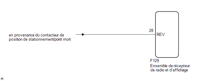
PROCEDURE
CHECK BACK-UP LIGHT OPERATION
(a) Shift the shift lever to R and check whether the back-up lights come on.
OK:
The back-up lights come on.
| NG |  |
GO TO EXTERIOR LIGHTING SYSTEM |
|

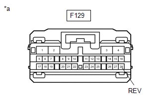
CHECK WIRE HARNESS AND CONNECTOR (REVERSE SIGNAL)
(a) Disconnect the radio receiver and display assembly connector.
(b) Measure the voltage according to the value(s) in the table below. Standard voltage:
|
|
| OK | |
GO TO APPLICABLE SYSTEM AS INDICATED IN THE PROBLEM SYMPTOMS TABLE |
| NG | |
REPAIR OR REPLACE HARNESS OR CONNECTOR |