Side panels

In this manual: Side panels
General information on preservation measures — 1Body cavity sealing — 1Body corrosion protection — 1Body repair instructions — 1Support members — 1Luggage compartment floor — 1Wheel wells — 1Side frame and door pillars — 1Roof outer skin — 1Dash cowl — 1Front trim panel — 1Rear trim panel — 1Side panels — 1Front side doors — 1Rear side doors — 1Front lid — 1Rear lid — 1Other flaps — 1Body special tools — 1General information — 1Handling brake fluids — 1Brake testing and bleeding — 1Front brakes — 1Rear brakes — 1Master brake cylinder — 1Brake lines — 1Brake booster — 1Electrical components/wear indicator — 1Parking brake — 1Mechanical/hydraulic components — 1Electronic components — 1Brakes — 1Front brake — 1Pedal mounting block — 1Brake pedal with linkage — 1Clutch pedal with linkage — 1Accelerator pedal actuation — 1Pedals — 1Specified grease — 1Propeller shaft, general — 1Propeller shaft assembly — 1Center console assembly — 1Front propeller shaft — 1Propeller shaft — 1Propeller shaft complete — 1Front axle repair instructions — 1Front axle suspension — 1Front sub-frame — 1Struts with rubber mounts — 1Wheel bearings and stub axle — 1Spring strut — 1Spring with suspension — 1Stabilizer bar — 1Front axle gearbox — 1Output shaft — 1Front axle — 1General information on high temperature multi-purpose grease — 1Rear axle repair instructions — 1Final drive with cover — 1Final drive mounting — 1Output shafts — 1Rear sub-frame — 1Control arms and struts — 1Axle mounting — 1Wheel bearings — 1Shock absorber — 1With suspension — 1Stabilizer bar — 1Rear axle — 1General information on final drive oil — 1Approved final drive oils for front and rear axle final drives with and without limited slip or viscous coupling — 1Final drive oil for bmw m1 motorsport coupe — 1Operating fluids as of 11/2015 — 1Brake pad replacement reminder — 1Emissions maintenance reminder — 1Maintenance service reminder — 1Tire pressure monitor system reminder — 1Description — 1Troubleshooting — 1Ignition wires, spark plugs — 1Ignition coil — 1Electronic switching or control units — 1Preheating relay — 1Preheater plugs — 1Alternator with drive and mounting — 1Controller — 1Starter with mounting — 1Starter lead — 1Engine wiring loom — 1Oil pressure/oil temperature/oil gauge — 1Switches and relays — 1Engine electrical system — 1Cabin air filter — 1Cabin air filter applications — 1Operating fluids - air conditioning and heating — 1Air conditioner refrigerant — 1Refrigeration oil — 1Note, overview components climate control — 1Heater with operation — 1Auxiliary. heater with control elements — 1Nozzles and outlets — 1Microfilter — 1Air conditioning, leak detection — 1Ac housing/evaporator, switching elements — 1Compressor — 1Condenser and dryer with lines — 1Heating and air conditioning — 1Front axle repair instructions — 1Front axle suspension — 1Front sub-frame — 1Struts with rubber mounts — 1Wheel bearings and stub axle — 1Spring strut — 1Spring with suspension — 1Stabilizer bar — 1Front axle gearbox — 1Front axle — 1General information on high temperature multi-purpose grease — 1Integrated suspension systems repair instructions — 1Front control and suspension elements — 1Rear control and suspension elements — 1Electrical components — 1Electronic damping force adjustment — 1Integrated suspension systems — 1Approved hydraulic fluids — 1Rear axle repair instructions — 1Final drive — 1Final drive with cover — 1Final drive mounting — 1Output shafts — 1Rear sub-frame — 1Control arms and struts — 1Axle mounting — 1Wheel bearings — 1Shock absorber — 1Springs with suspension — 1Stabilizer bar — 1Rear axle — 1General information on final drive oil — 1Approved final drive oils for front and rear axle final drives with and without limited slip or viscous coupling — 1Final drive oil for bmw m1 motorsport coupe — 1Operating fluids as of 11/2015 — 1Electronic chassis alignment — 1Mechanical steering gear — 1Steering gear with servo unit — 1Steering arms, tie rods, steer. damper — 1Steering column — 1Steering wheel — 1Steering wheel for airbag — 1Pump and oil supply — 1Steering and wheel alignment — 1Wheels — 1Disc wheels (rims) — 1Tires — 1Wheels with tires — 1Tire mounting paste — 1Engine mounting — 1Transmission suspension, automatic. transmission — 1Engine and gearbox suspension — 1Transmission in general — 1Transmission case, oil sump — 1Extension housing, bearings, seal — 1Mechanical attachments — 1Hydr/el control components/elements — 1Oil pump — 1Shift valves, parking lock — 1Torque converter — 1Automatic transmission — 1Automatic transmission fluid for zf-transmission GA8HP45Z / GA8HP50Z / GA8HP70Z / GA8HP90Z / GA8P70H / GA8P75H / GA8HP75Z — 1General information on automatic transmission fluids — 1Approved automatic transmission fluids for initial fillings and correcting fluid levels — 1Checking transmission fluid level — 1Transmission fluid change intervals (if applicable) — 1Transfer case, general — 1Transfer box — 1Transmission shafts — 1Transfer box special tools — 1Transfer box in general (atc 45l) — 1Transmission in general — 1Bearing in housing, sealing ring — 1SELF-DIAGNOSTICS DTCS — 1
~5min read
  • Removing and installing front side panel on left
  • Replacing left rear side panel
  • Stripping operations - replacing rear side panel, left

Removing and installing front side panel on left

Observe GAP DIMENSIONS.

IMPORTANT: Do not damage adjoining body components.

Necessary preliminary tasks:

  • Remove TRIM COVER FROM WHEEL ARCH at front left
  • Remove WATER COLLECTION STRIP ON WINDSCREEN
  • F25 only: Remove SIDE REPEATER
  • Partially detach FRONT WHEEL ARCH COVER
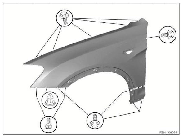
Body+and+Frame

Release screws.

Replacing left rear side panel

Read contents of BODY, GENERAL.

STRIP DOWN VEHICLE

Procedure OBSERVE repair stage 2! Following new body parts are required :

  • (1) Rear side wall
  • Reinforcement plate, side sill
  • Reinforcement plate, C-pillar
  • Reinforcement plate, D-pillar
  • Mounting nuts

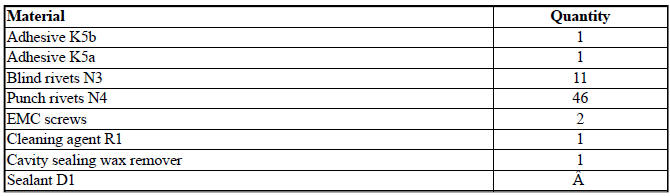
Following CONSUMABLES are required:
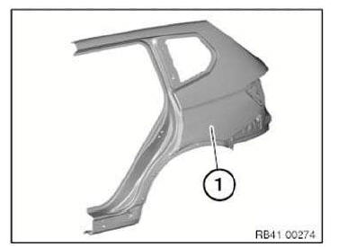
Body+and+Frame
Body+and+Frame

Removing side panel

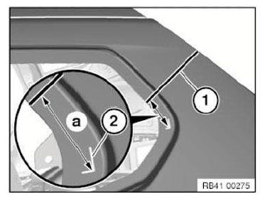
Mark dimension a for severance cut (1) on D-pillar.

Dimension a = approx. 75 mm from corner of mark (2).
Body+and+Frame

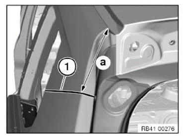
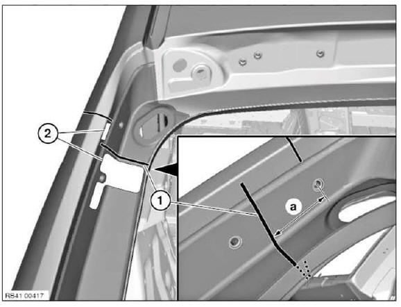
Mark dimension a for severance cut (1) on D-pillar.

Dimension a = approx. 135 mm from corner of roof frame.

Carry out severance cut (1).

IMPORTANT: Cut outer panel only.
Body+and+Frame

NOTE: In addition to the dimensions, the position of the separating cut can be determined with a TEMPLATE (1).
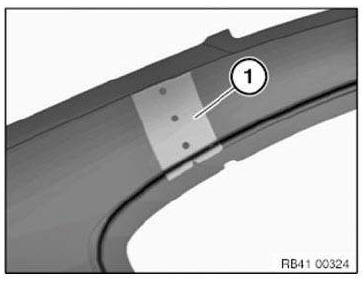
Body+and+Frame
Body+and+Frame

Mark severance cut (1) in accordance with dimension and cut.

Dimension a = approx. 60 mm from center point mounting bore for damper holder.

IMPORTANT: Cut outer panel only.

Severance cut (1) must be partially executed using a belt sander.

Open welded connections in areas (2).
Body+and+Frame

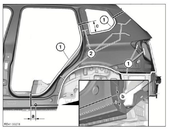
Mark severance cuts in accordance with specified dimensions and cut.

IMPORTANT: Cut outer panel only.

Compare position of severance cuts with REINFORCEMENT PLATES.

Dimension a = approx. 65 mm before center of 22 mm dia. hole.
Dimension b = approx. 20 mm from sill edge.
Dimension c = approx. 155 mm from side wall component edge.

Open welded connections in areas (1).

Release side wall from cavity sealing (2).

Open welded connections in areas (1).

Take off side wall.
Body+and+Frame

New part preparation

Mark severance cuts on the new part according to vehicle and cut.

Prepare REINFORCEMENT PLATES (bonded) at all severance cuts.

Mark severance cut (1) in accordance with vehicle and cut.

Mark severance cut (2) at sill edge and cut.

Mark further severance cuts in accordance with vehicle and cut.
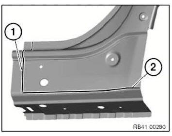
Body+and+Frame

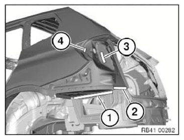
D-pillar water channel severance cut area: Make an additional 2 shims (1) and (2) in the severance cut area.

NOTE: Before installing the side wall:

Coat shim (1) with adhesive and slide in.

Coat shim (2) with adhesive and secure with a punch rivet N4.
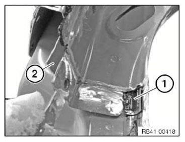
Body+and+Frame

Adjust new part to fit and secure.

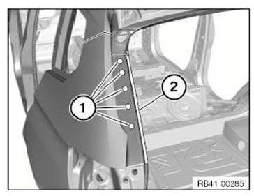
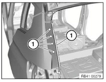
Set three 4.2 mm dia. holes for blind rivets in area (1).
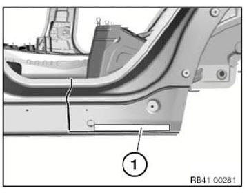
Body+and+Frame

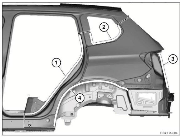
In areas (1) to (4), set 4.2 mm dia. bore holes for blind rivets.

Body+and+Frame
Body+and+Frame

Remove new part again and deburr bore holes.

IMPORTANT: Do not grind/sand new part in area of bonding surfaces.

Installing side wall

Clean all bonding surfaces on vehicle, on the new part and on the reinforcement plates with cleaning agent R1.

Apply adhesive to reinforcement plates. Install reinforcement plates.

Apply adhesive in areas (1).

Apply sealant to CAVITY ACOUSTIC BAFFLES in areas (2).
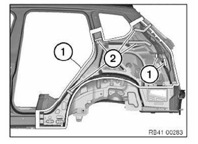
Body+and+Frame
Body+and+Frame

Install side panel with a second person helping.

NOTE: When installing side panel, make sure there is sufficient adhesive on bonding surfaces.

After adjusting side wall to fit, tighten nuts of reinforcement plates.

Align side wall in areas of severance cuts and fix with gripping pliers.

Rivet side wall with blind rivets N3.

In areas (1) to (4) rivet side panel with punch rivets N4.

Body+and+Frame

Rivet side wall with blind rivets N3.

In areas (1) and (2) rivet side panel with punch rivets N4.

Body+and+Frame
Body+and+Frame

Once the adhesive has hardened in area (1) and in the area of the side sill, fit one EMC SCREW in each area.
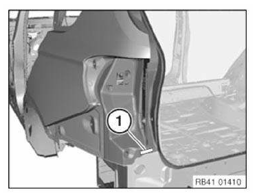
Body+and+Frame

Stripping operations - replacing rear side panel, left

NOTE: Owing to the different engine variants and equipment specifications, not all the components are taken into consideration.

The following list basically represents the removal sequence.

  • Disconnect negative battery cable
  • Remove bumper trim panel
  • Remove rear bumper guide middle (left side)
  • Remove left bumper guide
  • Remove tail panel cover at top
  • Remove luggage compartment floor trim panel
  • Remove left luggage compartment wheel arch panel
  • Remove rear left side window
  • Partially detach tailgate seal
  • Release holder for damper
  • Remove left rear light
  • Remove trim panel for left roof pillar
  • Remove left lock striker
  • Remove rear left door sill cover strip
  • Remove rear left rocker panel trim
  • Remove left backrest side section
  • Remove cover on C-pillar at bottom left
  • Remove rear left door edge protection
  • Remove rear left wheel arch cover
  • Remove cover on rear wheel arch
  • Remove trim panel for cover on left side member
  • Remove rear left underbody panelling
  • Remove rear left door
  • Remove trim strip on left roof frame

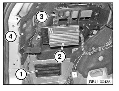
Undo latch mechanisms and remove rear bleeder (1).

Disconnect plug connections for control unit (2).

Remove bracket (3).

Remove insulating mat (4).

Installation note: The rear ventilation (1) must not be damaged. (watertightness).

All latch mechanisms must engage audibly.
Body+and+Frame

Test yourself

A quick BMW X3 quiz: every answer comes with an explanation and a link to the manual page.