Struts with rubber mounts
- Removing and installing left or right wishbone
- Removing and installing/replacing guide joint in swivel bearing
- Removing and installing/replacing left or right trailing link
- Replacing rubber mount in left or right control arm
- Replacing rubber mount in left or right trailing link
Removing and installing left or right wishbone
Special tools required:
- 31 2 242
- 31 2 246
- 31 2 240
NOTE: If the wishbone is detached from the front axle support, it will be necessary to carry out the wheel alignment procedure .
Necessary preliminary work:
- Remove FRONT WHEEL .
IMPORTANT: Do not release wishbone from swivel bearing with impact tool.
Check rubber boot and tension ring for damage! When reinstalling the wishbone, check the seal seat for the tension ring between wishbone and swivel bearing and replace wishbone, if applicable!
If necessary, remove link for ride-height sensor at wishbone on left.
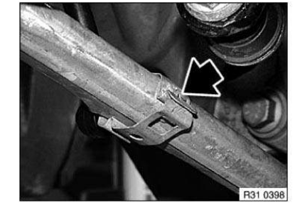
Release nut (1) approx. 3-4 thread turns; if necessary, counter support at Torx socket.
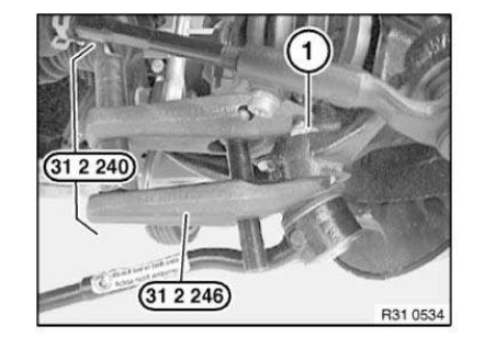
If necessary, replace lower section 31 2 242 with lower section 31 2 246 Use special tool 31 2 240 to press wishbone from swivel bearing.
Unscrew nut (1) and remove control arm.
Installation note: Keep journal on ball head and bushing in swivel bearing clean and free from oil and grease.
Replace self-locking nut.
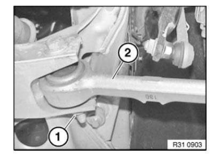
Slacken nut (1).
Remove bolt towards front, remove wishbone (2).
Installation note: Screw head must point in direction of travel.
Tighten down screw connection in NORMAL POSITION .
Replace screw and nut.
After installation:
- Carry out wheel alignment procedure .
REMOVING AND INSTALLING/REPLACING BOTH TRAILING LINKS
NOTE: The procedure is described in Removing and installing/replacing left or right trailing link.
Removing and installing/replacing guide joint in swivel bearing
Necessary preliminary work:
- Remove TENSION STRUT FROM GUIDE JOINT.
IMPORTANT: Check the rubber gaiter and circlip for damage! When removing and installing the trailing link, check the seat of the circlip seal between the trailing link and the wheel control joint and replace the wheel control joint if needed!
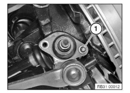
Release screw (1).
Remove guide joint from swivel bearing.
Installation note: Rework thread in swivel bearing.
Keep guide joint and bore hole in swivel bearing clean and free from oil and grease.
Replace microencapsulated screw.
Removing and installing/replacing left or right trailing link
Special tools required:
- 31 2 242
- 31 2 246
- 31 2 240
Necessary preliminary tasks:
- Remove FRONT WHEEL .
- Remove UNDERBODY PROTECTION.
- Partially loosen the LOWER WHEEL ARCH COVER (FRONT SECTION) .
IMPORTANT: Do not release trailing link from wheel control joint with impact tool! Check the rubber gaiter and circlip for damage! When removing and installing the trailing link, check the seat of the circlip seal between the trailing link and the wheel control joint and replace the wheel control joint if needed!
Release nut (1), if necessary, grip at inner Torx socket.
Installation note: Replace self-locking nut.
Perform steering angle.
Release screw (2).
Installation note: Rework thread in swivel bearing.
Replace microencapsulated screw.
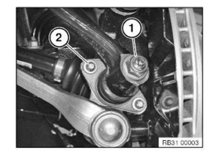
If necessary, screw nut (1) onto guide joint by a few turns.
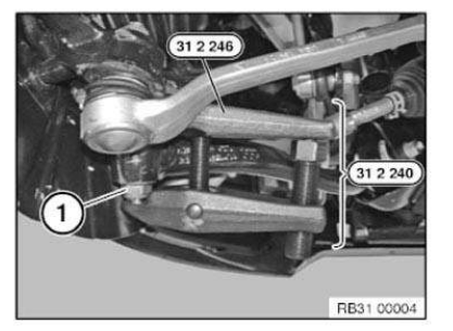
If necessary, replace lower section 31 2 242 with lower section 31 2 246 Press trailing link out of the guide joint with special tool 31 2 240 .
Unscrew nut (1) and remove trailing link.
Installation note: Keep journal on guide joint and bushing in tension strut clean and free from oil and grease.
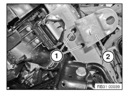
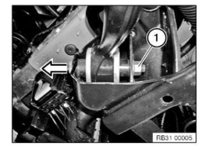
Slacken nut (1).
Remove screw towards front.
Remove tension strut.
Installation note: Replace screw and nut.
Tighten down screw connection in NORMAL POSITION .
Replacing rubber mount in left or right control arm
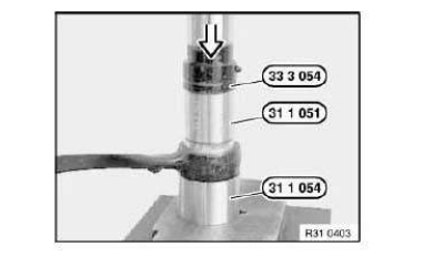
Special tools required:
- 31 1 051
- 31 1 054
- 33 3 054
NOTE: When replacing the rubber mount in the wishbone, a wheel alignment .
Necessary preliminary work:
- Remove WISHBONE.
Press rubber mount out with special tools 31 1 051 , 31 1 054 and 33 3 054 .
Installation note: Keep rubber mount and bore in control arm clean and free from grease.
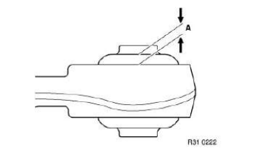
Press rubber mount in and out at chamfered side of wishbone bore hole.
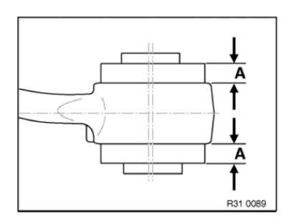
Installation note: Protrusion (A) = 5.74 Â+- 0.3 mm.
After installation:
- Carry out wheel alignment procedure .
Replacing rubber mount in left or right trailing link
Special tools required:
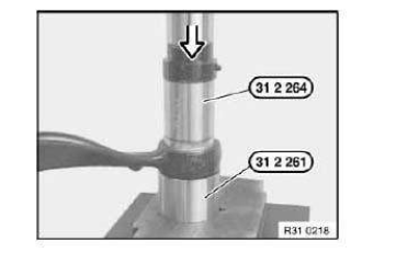
- 31 2 261
- 31 2 264
IMPORTANT: The rubber mounts are only permitted to be replaced once.
Carry out check: There must always be a minimum amount of play in the guide joint.
1. Check guide joint play
NOTE: Apply light pressure to the trailing link (in the area of the guide joint) in the horizontal and vertical directions.
Play is OK: Check the screw connection. (see Point 2) Play is not OK: Replace RUBBER MOUNT AND GUIDE JOINT.
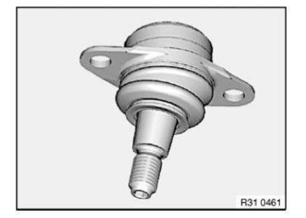
2. Check screw connection (trailing link to guide joint) by tightening to 60 % of tightening torque 31 12 2AZ and listening for cracking sound.
- Torque wrench cracking sound: Replace rubber mount
- Screw connection turns: Replace trailing link and guide joint .
Replacing rubber mount:
- Remove TRAILING LINK.
Using a press and special tools 31 2 261 and 31 2 264 , press rubber mount out of tension strut.
NOTE: Special tool 31 2 264 must be exactly flush with rubber mount bush.
Installation note: Keep rubber mount and bushing in tension strut clean and free from grease.
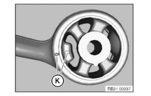
Align rubber mount and trailing link with markings (K) and press into place.
Installation note: Protrusion (A) equally large.
REPLACING RUBBER MOUNTS ON BOTH TRAILING LINKS
NOTE: Procedure is described in 31 12 138 Replacing rubber mount in left or right trailing link.
Test yourself
A quick BMW X3 quiz: every answer comes with an explanation and a link to the manual page.