Piston Pins and Rings
GENERAL INFORMATION
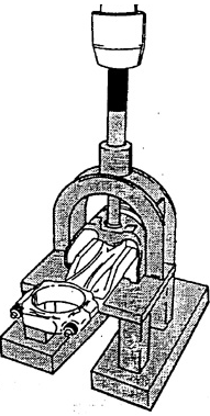
Removal of piston pin
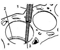
Measuring piston ring end gap
1. FEELER GAUGE.
2. PISTON RING.
3. RING END GAP, WITH RING INSTALLED IN CYLINDER AT BOTTOM POSITION

Measuring piston ring side clearance in groove. MEASURING RING SIDE CLEARANCE WITH FEELER GAUGE
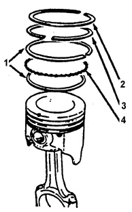
Piston assembly with connecting rod
1. OIL CONTROL RING.
2. UPPER COMPRESSION RING.
3. LOWER COMPRESSION RING.
4. EXPANDER RING

Installation of piston pin

Location of piston ring end gaps
1. EXPANDER RING END GAP.
2. OIL CONTROL RING END GAP.
3. LOWER COMPRESSION RING END GAP.
4. UPPER COMPRESSION RING END GAP
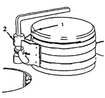
Installation of piston into cylinder
1. THE MARK ON THE PISTON CROWN MUST FACE THE FRONT OF THE ENGINE.
Disassembly
PROCEDURE.
1. Remove the piston rings using a ring expander. Removed rings must not
be reused..
2. Place the piston and connecting rod assembly in the fixture and press out the
piston pin, refer to illustration. Removal of piston pin..
Clean.
PROCEDURE.
Piston, pin and connecting rod. Clean from
– dirt.
– carbon deposits.
– varnish deposits. Piston ring grooves must be cleaned down to bare metal..
Varnish deposits are removed from piston pins after soaking them in
carburetor cleaning fluid..
Warning.
To avoid poisoning, avoid inhaling vapors and contact
of solvent with exposed areas of skin..
Do not scrape the piston skirt..
Inspection
PROCEDURE.
1. Connecting rod..
1a. Check for bending or twisting distortion.
– Install the lower cap on the connecting rod and tighten the connecting rod bolts to the specified
torque.
– Install the connecting rod assembly on the alignment fixture and check for distortion
bending and twisting..
1b. Distorted connecting rods cannot be repaired and must be replaced. Before installation, check the shape of the new connecting rod..
1c. Check the bearing seats in the lower connecting rod head for signs of wear and roughness..
1d. Check the connecting rod bolts for residual stretch deformation,
comparing their length with new bolts..
1e. Check the upper connecting rod bushing for scoring..
2. Piston pin.
2a. Check for scoring..
2b. Check for wear caused by incorrect installation..
2c. Pin fit in the connecting rod bushing and piston bosses..
3. Piston.
3a. Check the skirt for scoring..
3b. Check for cracks..
3c. Damage to the piston ring groove walls..
3d. Wear..
Measure
PROCEDURE.
1. Piston rings..
1a. Select a new set of piston rings.
1b. Measure the ring end gap with a feeler gauge, refer to Measuring Piston Ring End Gap. Install the ring in the cylinder to a height corresponding to
the bottom dead center of the piston. Use the piston as a tool to move the ring.
Measure the ring end gap, refer to Measuring Piston Ring End Gap. If the gap is less than specified, carefully file
the butt ends of the ring..
1c. Measure the side clearance of the compression ring. Insert the compression
ring into the upper piston groove and measure the side clearance with a feeler gauge, refer to
Measuring Ring Side Clearance in Groove. If the ring is too high,
try to select a suitable ring. If necessary, ensure
proper fit of the ring in the groove. Grind the ring height to the required size.
Lap the ring using emery paper on a glass plate backing..
Warning.
Boring of piston grooves is prohibited. Carefully remove large irregularities in the grooves with the tip of a file..
Assembly.
PROCEDURE.
1. Connecting rod with piston..
Warning.
When assembling, orient the piston relative to the connecting rod so that
the mark on the piston (refer to Piston Assembly with Connecting Rod) is located on the side
of the connecting rod facing the front of the engine..
1a. Place the piston and connecting rod in a screw press, refer to Installation of Piston Pin. 1b. Adjust the position of the press screw..
1c. Lubricate the piston pin with clean engine oil..
1d. Press the pin into the piston..
Inspection
PROCEDURE.
Free movement of the piston relative to the pin..
Installation
PROCEDURE.
1. Oil control ring set.
– expander ring.
– lower oil control ring.
– top oil control ring.
2. Top and bottom compression rings. The markings on the rings must face upward..
Warning.
Use a piston ring installer or other tool to install the rings on the piston..
Do not expand the rings excessively, as this may break the ring..
To ensure a reliable gas seal in the cylinder, rotate the
rings so that the ring gaps are positioned as shown, Fig..
Piston ring gap positions..
3. Lubricate the cylinder bore and piston rings with clean engine oil..
4. Rotate the crankshaft to the bottom dead center position..
5. Install the protective rubber hoses on the connecting rod bolts..
6. Install the piston ring compressor, Fig. Installing the piston into the
cylinder..
7. Position the piston and connecting rod assembly so that the mark on the piston crown faces forward. Insert the piston into the cylinder..
Warning.
Use care when lowering the piston into the cylinder to avoid
damaging the crankshaft journal with the lower end of the connecting rod..
8. Remove the protective rubber hoses..
9. Install the connecting rod bearing inserts..
10. Install the connecting rod bearing cap..
Warning.
Seat the bearing cap in place with light taps of a hammer. Do not pull
the cap down with the bolts. Tighten the connecting rod bolts, then loosen by one turn and
tighten to the specified torque..
Inspection
PROCEDURE.
Push the connecting rod and move it back and forth to check for
free movement of the connecting rod.
Test yourself
A quick Daewoo Nexia quiz: every answer comes with an explanation and a link to the manual page.