Bearing shell replacement
GENERAL INFORMATION
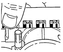
Main bearing clearance measurement

Installation of crankshaft thrust bearings.
1. THRUST FLANGES OF CENTER MAIN BEARING.
2. WOODEN BLOCK
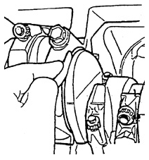
Crankshaft end play measurement
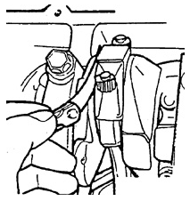
Connecting rod side clearance measurement
Depending on the condition of the crankshaft journals, bearing shell replacement
can be performed either without removing the engine or after removing the engine from the
vehicle. If the engine is removed from the vehicle, bearing shell replacement should be performed
in accordance with the instructions below and taking into account the features
of the specific engine type. Before replacement, check the condition of the main
bearings. On an engine removed from the vehicle and turned over, the crankshaft rests
on the upper bearing supports. Measure the main bearing clearance between the lower supports and
the journals. If clearances are measured on the engine without removing it from the vehicle,
lift the crankshaft up to take up the clearance between the shaft and the upper main bearing supports, and measure the clearance between the journals and the lower
bearing shells.
Bearing shell replacement with crankshaft removal.
PROCEDURE.
1. Remove the main bearing caps with bearing shells. Remove the bearing shells..
2. Remove the crankshaft. Check the condition of the crankshaft journals..
3. Remove the bearing shells from the cylinder block main bearing saddles..
4. Lubricate the bearing surfaces of the new bearing shells of the correct size and install them in the main bearing saddles of the block and in the bearing caps..
5. Install the crankshaft and secure the main bearing caps..
Bearing shell replacement without crankshaft removal.
PROCEDURE.
1. Remove the oil pan, oil pump, and unscrew the spark plugs..
Remove the main bearing cap requiring bearing shell replacement..
Remove the bearing shell from the cap..
2. Install the bearing shell installation tool in the oil
passage of the crankshaft journal. If the tool is not available, use
a cotter pin, bent to shape..
3. Turn the crankshaft clockwise when viewed from the front of the engine. The bearing shell located in the main bearing saddle will rotate together with the
shaft and come out..
4. Lubricate the new bearing shell and insert it plain side (without tang) between the journal
and the main bearing saddle of the block, from the side with the tang recess.
bearing shell. Rotate the bearing shell into position and remove the installation tool from the
oil passage in the journal..
5. Lubricate the new bearing shell and install it in the main bearing cap..
6. Install the bearing cap. The arrow on the cap must point toward the
front of the engine..
7. Tighten the main bearing cap bolts to 50 N·m + (40–60°)..
Inspection
PROCEDURE.
1. Check the bearing friction surfaces for
– wear.
– grooves.
– embedded foreign particles. If such defects are present, determine the type
of these particles and their origin. Inspect the sludge and deposits in the oil pan.
2. Check the outer surfaces of the bearings for
– wear. Signs of wear indicate either bearing shell movement or
significant irregularities on the mating parts.
– signs of overheating.
– signs of loosening and rotation (deformed tang,
circumferential grooves)..
3. Check the thrust surfaces (center main bearing) for
– wear.
– circumferential grooves. Grooves are worn due to irregularities of the thrust faces
of the crankshaft..
Warning.
If defects of the bearing shells are found, other than normal operational wear,
wear, carefully inspect the mating parts: crankshaft, main bearing bore, bearing cap, connecting rod.
main bearing bore, bearing cap, connecting rod.
4. Bearing cap bolts. If the bolts are stretched, they must be replaced.
Measure
To correctly determine the bearing shell size, carefully measure the bearing clearances. Any of the methods described below may be used.
measurement. However, Method A is preferred, as it provides more reliable results.
Warning.
In Method A, measurements are used to calculate the clearance. Method B
involves directly measuring the clearance. In addition, Method B
does not allow determining the bearing runout.
Do not install bearing shells of different nominal sizes in one main bearing.
main bearing.
METHOD
PROCEDURE.
1. Measure the crankshaft main journal diameter with a micrometer. Take measurements
at several points along the length of the journal, in sections spaced 90 degrees apart.
Average the measurement results.
2. Measure the journal taper and out-of-round.
3. Measure the inside diameter of the bearing shells with a micrometer. When replacing
bearing shells, take measurements with the new bearing shells.
Warning.
During measurements, the bearing cap bolts must be tightened to the specified
torque.
If the journal dimensions and out-of-round/taper are within the allowable limits,
select a bearing shell set of the appropriate size. If the journals are worn beyond
the allowable limit, grind the crankshaft journals to the undersize
repair size and install an undersize bearing shell set.
METHOD
PROCEDURE.
1. Install the bearing shells in the cylinder block bearing bores and on the crankshaft.
2. Place a plastigage strip across the full width of the main bearing journal.
bearing journal.
3. Install the bearing cap in place, carefully tapping the cap from above. Caution:
To avoid damage to the cylinder block and/or main bearing caps, use a hammer with a brass or lead head, or a soft-faced mallet with a leather face.
Do not seat the cap by tightening the mounting bolts. Failure to follow these instructions may damage the cylinder block or bearing caps.
Do not seat the cap by tightening the mounting bolts.
Failure to follow these instructions may damage the cylinder block
or bearing caps.
4. Tighten the bolts to the specified torque.
Warning.
Do not rotate the crankshaft.
5. Remove the bearing cap, leaving the plastigage strip in place.
6. Measure the maximum width of the crushed plastigage strip using the scale printed on the plastigage envelope. See illustration. Measuring the main bearing clearance.
Measuring the main bearing clearance.
main bearing clearance.
7. Completely remove the plastigage strip.
8. Select a bearing shell set that provides the required clearances in the
bearing.
Installation or connection.
Warning.
Main bearing shells must not have scratches, file marks, or
must be installed in the bores without additional shims. Do not touch the bearing shell friction surfaces with your hands, as finger oils can leave marks on the bearing coating.
Do not touch the bearing shell friction surfaces with your hands, as finger oils can leave marks on the bearing coating.
Make sure the cap bores and the mating surfaces of the caps and block bearing bores are clean. The rear main bearing cap seal installation procedure is described below.
PROCEDURE.
1. Dip the cap bolts in clean engine oil.
2. Install the bearing shells in the main bearing bores of the block and in the caps.
Warning.
Upper and lower bearing shells may differ. Make sure the oil holes align.
Do not block any oil passages.
The bearing shells protrude slightly when installed in their seats.
Make sure the shells protrude equally on both sides. Make sure the bearing shell tabs are correctly positioned.
Make sure the bearing shell tabs are correctly positioned.
3. When installing the thrust main bearing, lubricate the thrust surfaces.
4. Lubricate the bearing friction surfaces with clean engine oil.
5. Crankshaft.
Warning.
Care must be taken to avoid damaging the crankshaft journals. It is recommended
protective caps on the connecting rod bolts or guide pins.
guide pins.
6. Bearing caps. Carefully seat the caps in their places, lightly tapping them with a suitable tool.
with a suitable tool.
Warning.
To avoid damage to the cylinder block and/or main bearing caps, use a hammer with a brass or lead head, or a soft-faced mallet with a leather face.
Do not seat the cap by tightening the mounting bolts. Failure to follow these instructions may damage the cylinder block or bearing caps.
Do not seat the cap by tightening the mounting bolts.
Failure to follow these instructions may damage the cylinder block
or bearing caps.
7. Screw in the bearing cap bolts. Tighten the bolts evenly, then loosen them by one turn and tighten to the specified torque.
to the specified torque.
8. Install the thrust main bearing. See illustration. Installing the crankshaft thrust bearings. Move the shaft alternately in both directions to align the shaft thrust surfaces with the center main bearing.
Inspection
PROCEDURE.
Check that the connecting rods move freely and do not bind. If necessary, loosen the main bearing cap bolts and retighten them.
Measure
PROCEDURE.
1. Crankshaft end play. See illustration. Measuring the crankshaft end play.
2. Connecting rod side clearances. See illustration. Measuring the connecting rod side clearances.
Test yourself
A quick Daewoo Nexia quiz: every answer comes with an explanation and a link to the manual page.