Cylinder Head. Camshaft Housing
GENERAL INFORMATION
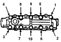
Cylinder Head Bolt Removal Sequence
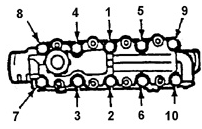
Cylinder Head Bolt Tightening Sequence
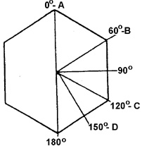
Cylinder Head Bolt Tightening Stages
Warning.
When removing the cylinder head or camshaft housing, always replace
the head gasket. Loosen the cylinder head bolts only when the engine is cold. Use new bolts during assembly.
Remove or disconnect:
PROCEDURE.
1. Lower radiator hose..
2. Drain coolant..
3. Disconnect the negative battery cable.
4. Pivot the alternator bracket aside after moving the alternator outward.
5. Distributor 14 with leads.
6. Cables from:
– intake manifold bracket.
– throttle body.
– downshift switch.
7. All vacuum hoses from the throttle body and intake manifold.
8. Hoses.
– fuel lines (supply and return);.
Warning.
Fuel lines are under pressure. Do not disconnect hoses until
fuel system pressure is relieved.
– engine cooling and heater hoses from the lower part of the housing.
throttle body and the hose from the washer pump inlet fitting.
– hose from cap B and crankcase ventilation (PCV) fitting 155 from housing 8.
– upper radiator hose..
9. Exhaust pipe from exhaust manifold..
10. Oxygen sensor connector..
11. Electrical wires.
– fuel injection system.
– spark plugs..
12. Timing belt..
13. Unscrew the cylinder head bolts in the sequence shown in Fig. Cylinder head bolt removal sequence. (Engine must be cold)..
14. Camshaft housing 8..
15. Cylinder head assembly with exhaust and intake manifolds 53,
23..
Clean.
PROCEDURE.
1. Clean oil and dirt from the mating surfaces of the head, camshaft housing and
cylinder block. Mating surfaces must not have dents or deep scratches..
2. Cylinder head bolts and threaded holes in the cylinder block must be clean. If dirt gets into the holes, the seal may be compromised.
parts when tightening bolts to nominal torque..
Installation
PROCEDURE.
1. Apply a continuous 3 mm bead of sealant to the sealing
surface of the camshaft housing..
2. Install cylinder head 29 and new gasket 26 (connect intake and exhaust manifolds if they were removed)..
3. Install camshaft housing 8 onto the cylinder head upper plate..
4. Install new cylinder head bolts 4. When tightening bolts, follow the sequence shown in Fig. Cylinder head bolt tightening sequence..
4a. Tighten all cylinder head bolts 29 to torque 25 N·m..
4b. Additionally turn bolts 60° (see Fig. Tightening stages.
cylinder head bolt tightening)..
4c. Additionally turn bolts 60°..
4d. Additionally turn bolts 30°..
5. Hydraulic lash adjusters 37 and rocker arms
36..
6. Timing belt
44..
7. Electrical wire connectors.
– fuel injection system.
– spark plugs..
8. Exhaust pipe to exhaust manifold..
9. Oxygen sensor connector..
10. Hoses.
– upper radiator hose.
– crankcase ventilation hose.
– hose to the lower part of the throttle body housing and water pump pressure hose.
– fuel lines (supply and return)..
11. Reposition all vacuum hoses secured to the
throttle body and intake manifold..
12. Cables to:
– intake manifold bracket.
– fuel injection system throttle body.
– low gear switch..
13. Ignition distributor 14 with wires..
14. Generator bracket, generator, belt. Adjust belt tension..
15. Lower radiator hose..
16. Battery negative cable..
17. Refill coolant..
18. Start the engine and warm it up to thermostat opening temperature..
19. Tighten the cylinder head bolts an additional 30°–50° in the
sequence shown in Fig. Cylinder head bolt tightening sequence.
cylinder head bolts.
Test yourself
A quick Daewoo Nexia quiz: every answer comes with an explanation and a link to the manual page.