Main components of the transaxle
GENERAL INFORMATION

HYDRA-MATIC 4T40E transaxle
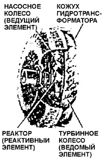
Torque converter

Torque converter fluid flow diagram (without stator)
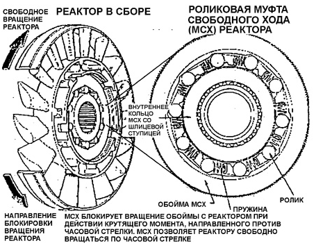
Stator assembly with roller one-way clutch

Torque converter fluid flow diagram with stator held stationary
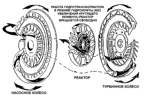
Torque converter fluid flow diagram with stator freewheeling
The automatic transaxle consists of three main components: the planetary gear set, the torque converter and the hydraulic control system.
The automatic transaxle consists of three main components: the planetary gear set, the torque converter and the hydraulic control system.
The torque converter (TC) performs two main functions: it transmits engine torque smoothly to the transaxle and multiplies torque when the load increases.
The torque converter (TC) performs two main functions: it transmits engine torque smoothly to the transaxle and multiplies torque when the load increases.
The torque converter (TC) performs two main functions: it transmits engine torque smoothly to the transaxle and multiplies torque when the load increases.
The torque converter consists of three main components: the impeller (driving element), the turbine (driven element) and the stator (reaction element).
The torque converter consists of three main components: the impeller (driving element), the turbine (driven element) and the stator (reaction element). The impeller is welded to the converter cover. The annular space inside the converter cover is filled with transmission fluid. The converter cover is bolted to the drive plate with ring gear, which meshes with the starter pinion. The drive plate is mounted directly on the engine crankshaft. Therefore, the impeller is rigidly connected to the crankshaft and always rotates at the same speed as the crankshaft.
The impeller is welded to the converter cover. The annular space inside the converter cover is filled with transmission fluid.
The converter cover is bolted to the drive plate with ring gear, which meshes with the starter pinion. The drive plate is mounted directly on the engine crankshaft. Therefore, the impeller is rigidly connected to the crankshaft and always rotates at the same speed as the crankshaft.
speed as the crankshaft.
When the engine is running, the impeller works as a centrifugal pump, forcing the fluid (oil) to flow from the center to the periphery of the impeller between its
blades. At the same time the fluid gains tangential velocity directed clockwise.
blades. At the same time the fluid gains tangential velocity directed clockwise.
At the outlet of the impeller passages the fluid enters the turbine blades. Due to the special shape of the turbine blades, the fluid flow changes direction, exerting force on the turbine and causing it to rotate in the same direction as the impeller.
At the outlet of the impeller passages the fluid enters the turbine blades. Due to the special shape of the turbine blades, the fluid flow changes direction, exerting force on the turbine and causing it to rotate in the same direction as the impeller.
When the engine is running at idle, the energy transferred to the fluid by the impeller is small, and the torque developed on the turbine is also small.
When the engine is running at idle, the energy transferred to the fluid by the impeller is small, and the torque developed on the turbine is also small.
With a gear engaged and the engine idling, the turbine torque is insufficient to move the vehicle from a standstill. Increasing the throttle opening increases impeller speed, the kinetic energy of the fluid, the hydrodynamic forces on the turbine blades and, accordingly, the torque on the input shaft of the transaxle.
With a gear engaged and the engine idling, the turbine torque is insufficient to move the vehicle from a standstill. Increasing the throttle opening increases impeller speed, the kinetic energy of the fluid, the hydrodynamic forces on the turbine blades and, accordingly, the torque on the input shaft of the transaxle.
Increasing the throttle opening increases impeller speed, the kinetic energy of the fluid, the hydrodynamic forces on the turbine blades and, accordingly, the torque on the input shaft of the transaxle.
transaxle.
The working fluid, transferring energy to the turbine wheel, flows through the turbine vane passages from the periphery toward the center, and at the exit from the turbine wheel it acquires a tangential velocity directed counterclockwise.
The torque transmitted from the engine to the turbine wheel arises due to
a change in the direction of flow of the working fluid as it passes through the turbine vane passages. The magnitude of the torque depends on the change in angular momentum
of the working fluid at the inlet and outlet of the turbine wheel. To swirl the working fluid flow leaving the turbine wheel and impart rotation to it,
a stator (reactor) installed between the outlet of the turbine and the
inlet of the pump wheel is used. The stator ensures shock-free entry of the working fluid onto the pump wheel blades and high pump efficiency.
The function of the stator is to change the direction of the tangential velocity of the working
fluid circulating in the torque converter. The tangential velocity of the fluid at the stator inlet is
directed counterclockwise. At the stator outlet, the working fluid
acquires a tangential velocity directed clockwise and coinciding with the direction of rotation of the pump wheel. Due to the action of the stator, the kinetic
energy of the working fluid at the outlet of the pump wheel and the torque on the
turbine wheel increase. The turbine torque exceeds the engine torque.
The flow of working fluid passing through the stator vane passages acts on the stator wheel in the counterclockwise direction and locks
the stator through the one-way clutch (OWC), which keeps the stator stationary in torque converter mode.
With the accelerator pedal fully depressed and the vehicle stationary, the torque
on the turbine of the torque converter will have its maximum value, exceeding the
engine torque.
As the turbine speed of the torque converter increases and the vehicle accelerates, the direction of flow of the working fluid leaving the turbine wheel vanes will change.
At a certain ratio of rotational speeds of the pump and turbine wheels,
the direction of the torque acting on the stator vanes from the fluid flow
will reverse and the OWC releases the stator. The stator will rotate freely without affecting the flow of working fluid circulating in the torque converter. In this
case the torque converter operates in fluid coupling mode without torque multiplication.
The rotational speeds of the pump and turbine wheels in this operating mode differ only slightly.
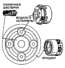
Planetary gear set
The planetary gear set serves to increase engine torque. The name "planetary" is related to the design features of the gear set, which is characterized by
orbital motion of the gears. All gears of the planetary gear set are in
constant mesh, which eliminates shock engagement of gears that could occur when gears are brought into mesh with each other. At each gear stage of the planetary
gear set, several gears are in mesh simultaneously, which share the load between them. This contributes to greater strength and lower mass of the planetary gear set. Due to the coaxial arrangement of the input and output shafts, the planetary gear set is very compact.
The planetary gear train consists of the sun gear, ring gear with internal teeth, planet carrier and planet gears, which perform relative and orbital motion.
The planetary gear set can increase torque or rotational speed of the output shaft, reverse the direction of rotation of the output shaft, and rigidly connect the input and output shafts directly.
When the gear set operates in torque-increasing mode, it is said that the reduction gear stage is engaged, since the angular speed of the output shaft is reduced compared with the input shaft speed. At a constant input shaft speed, the torque and the angular speed of the output shaft change in inverse proportion.
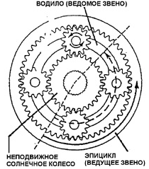
Reduction gear stage
The reduction gear stage is obtained with the sun gear held stationary and the ring gear driving.
When the ring gear rotates, the planet gears, rolling around the stationary sun gear,
drive the planet carrier (driven member of the planetary gear set) at a reduced speed. The planet carrier rotates in the same direction as the ring gear.
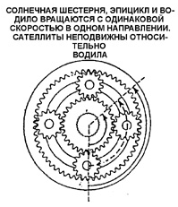
Direct drive
Direct drive is obtained by rigidly connecting any two members of the planetary gear set.
In this case all members rotate at the same speed. The planet gears
remain stationary relative to the planet carrier, locking the sun gear and ring gear together.
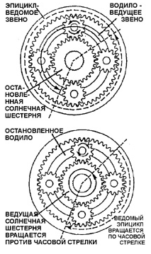
Overdrive stage. Overdrive stage (top) and reverse gear (bottom).
The overdrive stage is obtained with the sun gear held stationary and the planet carrier driving.
The planet carrier rotates together with the planet gears, which roll around the stationary sun gear and drive the ring gear at a higher speed than
the planet carrier speed.
Reverse gear.
Reversal of the direction of rotation of the driving member is obtained with the planet carrier held stationary.
The driving member may be either the sun gear or the ring gear.
Accordingly, the driven member will be the ring gear or the sun gear. In this case
the planet gears rotate about stationary axes and act as idler gears. Regardless of which member is driving (sun gear or ring gear), the driven member of the planetary gear set will rotate in the opposite
direction relative to the driving member.
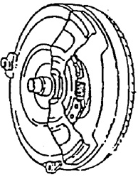
Torque converter lock-up clutch

Lock-up clutch operation diagram
When the torque converter lock-up clutch is engaged, the clutch plate is connected to the torque converter cover and
engine power is transmitted directly to the turbine wheel shaft. Lock-up
eliminates slip of the torque converter. A spring damper is built into the hub of the lock-up clutch plate, reducing dynamic loads in the drivetrain during lock-up. The damper allows axial movement and relative rotation of 45 degrees.
Multi-plate clutches
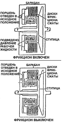
Multi-plate clutch operation diagram
Multi-plate clutches are engaged hydraulically by means of annular pistons.
control (servo) cylinders.
Cam-Type One-Way Clutches

Cams and Cage of One-Way Clutch
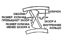
Cam-Type One-Way Clutch Diagram
A one-way clutch allows the component installed on it to rotate.
in one direction only..
A one-way clutch consists of an inner race, an outer race, and cams with a cage..
The cam has a special symmetrical profile. One of its cross-sectional dimensions
is larger and the other is smaller than clearance A between the inner race and the outer race. When rolling, the cams either lock with each other or
release the inner race and the outer race. As a result, relative rotation of the parts is possible in only one direction.
Test yourself
A quick Daewoo Nexia quiz: every answer comes with an explanation and a link to the manual page.