Combination Switch, Steering Shaft, Steering Column (Tilt Type)
GENERAL INFORMATION

Tilt steering column for vehicles with automatic transmission and manual transmission
1. NUT.
2. TURN SIGNAL CANCELLING SPRING.
3. SNAP RING
4. RETAINER.
5. UPPER BEARING SPRING.
6. SCREW.
7. COMBINATION SWITCH MOUNTING HOUSING.
8. SEAT.
9. INNER RING.
10. SHEAR BOLT.
11. WASHER.
12. TILT HOUSING.
13. TILT HOUSING PIVOT.
14. IGNITION LOCK MOUNTING BRACKET.
15. IGNITION SWITCH.
16. SET SCREW.
17. STEERING WHEEL TILT ANGLE ADJUSTING MECHANISM SPRING.
18. SPRING RETAINER.
19. UNIVERSAL JOINT STEERING SHAFT ASSEMBLY.
20. UPPER STEERING SHAFT.
21. HEMISPHERICAL SHOE.
22. SPRING.
23. LOWER STEERING SHAFT.
24. TILT HOUSING STOPPER.
25. BOLT.
26. STEERING COLUMN SUPPORT.
27. STEERING COLUMN JACKET
Remove or disconnect
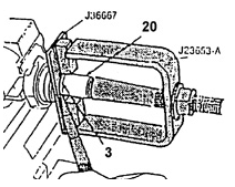
Removal and Installation of Snap Ring
3. SNAP RING
20. UPPER STEERING SHAFT
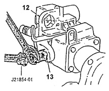
Removal of Steering Column Tilt Housing Pivot Pins
12. TILT HOUSING
13. TILT HOUSING PIVOT
PROCEDURE.
1. Steering wheel.
2. Steering column assembly.
3. Remove guide bushing 28 from the lower end of steering shaft 19 (if not removed previously).
removed previously.
4. Remove spring 2 from the upper end of shaft 19 (if not removed previously).
5. Remove screws
6..
6. Remove combination switch housing 7.
7. Compress spring 5 using the retainer
4..
8. Snap ring 3, retainer 4, spring 5, seat 8 and inner ring 9.
9. Pull the tilt lever located on housing 12 and raise the steering wheel up to the stop.
10. Insert a Phillips screwdriver into the square hole of retainer 18,
press down, and turn the screwdriver counterclockwise to release retainer 18 and the spring.
17..
11. Retainer 18 and spring
17..
12. Two pivots
13..
13. Turn the lock cylinder to the "RUN" position (ignition on).
14. Pull the tilt lever and remove the tilt housing
12 from the steering column support 26.
15. Remove shear bolts 10, washers 11, and separate ignition lock mounting bracket 14 from the tilt housing
12..
15a. Drill out the heads of shear bolts 10 down to the steel washers
11. Use a
6.5 mm drill. Refer to the illustration. Initial and final positions of the shaft gear. 15b. Remove washers 11 and separate bracket 14 from tilt housing 12 of the steering
column.
15c. Remove the bolt shanks 10 from bracket 14 using pliers.
Warning.
After drilling out the bolt heads, clean the parts of metal chips.
metal chips.
16. Remove the ignition lock cylinder from housing 14.
17. Unscrew the set screw.
16..
18. Remove the ignition switch 15 assembly.
19. Remove steering shaft 19 assembly through the bracket opening.
26..
20. Remove stops 24 using pliers.
21. Remove bolts 25 and disconnect bracket 26 from the flange of steering column shroud 27.
Disassemble
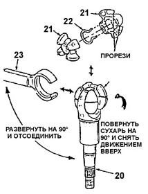
Disassembly and Assembly of Steering Shaft Joint
20. UPPER STEERING SHAFT.
21. HEMISPHERICAL SHOE.
22. SPRING.
23. LOWER STEERING SHAFT
If necessary, repair steering shaft joint 19 as follows.
Refer to the procedure below.
Warning.
Before disconnecting upper shaft 20 and lower shaft 23 from each other, mark the relative position of the longitudinal groove on shaft 20 and the flat
for the clamp bolt on the shaft.
23. If steering shaft 19 is turned so that the groove for the
steering lock tab is at the top (clock hand at 12 o'clock), the flat must
correspond to the clock hand pointing to 7 o'clock. During assembly, the steering shaft parts must be installed in the
pointing to 7 o'clock. During assembly, the steering shaft parts must be installed in the
same position.
PROCEDURE.
1. Turn steering shaft 20 90 degrees relative to lower shaft 23 and
disconnect the latter from the joint. See illustration: Removal of Steering Column Pivot Housing Pins.
Steering Column.
2. Turn the spherical pin 90 degrees and remove it from the fork of shaft 20.
3. Separate the half-spherical pins 21 and remove the preloaded
spring.
22..
Assembly
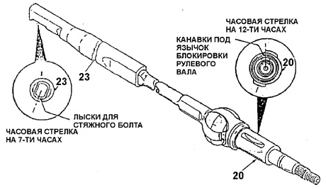
Correct Relative Position of Upper and Lower Steering Shafts
20. UPPER STEERING SHAFT.
23. LOWER STEERING SHAFT
PROCEDURE.
1. Lubricate half-spherical pins 21 and spring 22 with lithium grease.
2. Install spring 22 between half-spherical pins 21, inserting the ends of the
spring into the corresponding slots of the pins. See illustration: Removal of Steering Column Pivot Housing Pins.
Steering Column Pivot Housing.
3. Lubricate the fork of upper shaft 20 with lithium grease.
4. Insert the pin assembly 21 into the fork of shaft 20 and turn them 90 degrees.
5. Lubricate the fork of lower shaft 23 with lithium grease.
Warning.
To correctly assemble upper 20 and lower 23 steering shafts, perform the
following. Turn upper shaft 20 so that the groove for the steering lock tab
is at the top (clock at 12 o'clock). The flat on the end of
lower shaft 23 must be located at the bottom left (clock at 7 o'clock),
see illustration: Correct Relative Position of Upper and Lower Steering Shafts.
6. Turn upper shaft 20 90 degrees relative to lower shaft 23.
23..
7. Insert the fork of shaft 23 into the joint and straighten the steering shaft assembly.
Installation
Warning.
All fasteners used in the installation operations described below
must be tightened firmly before final tightening to the specified torque
value.
PROCEDURE.
1. Install bracket 26 to flange of shroud 27 using bolts
25. Tighten bolts to torque 16 N·m.
2. Install stops 24 on bracket 26 and install spring ring in place.
3. Insert steering shaft 19 into the bracket opening.
26..
4. Lubricate both bearings of column pivot housing 12 with lithium grease.
5. Install housing 12 onto shaft 19 and into the bracket.
26..
6. Lubricate pins 13 with lithium grease.
7. Insert pins 13 into the holes of housing 12 until they stop.
Warning.
After installation, stake pins 13 in housing
12. Stake each pin at
three points evenly spaced around the circumference.
8. Pull the tilt adjustment lever and raise the steering wheel to the maximum upward position.
Raise the steering wheel to the maximum upward position.
9. Lubricate spring 17 of the steering wheel tilt adjustment mechanism with
lithium grease.
10. Spring 17 and retainer
18. Make sure the end of spring 17 is hooked onto the bracket hook
26. Insert a Phillips screwdriver into the square hole of
retainer 18 of the spring, press down and turn the screwdriver clockwise to
lock the retainer.
18..
Warning.
To ensure the lock cylinder tab and the groove of ignition switch 15 match during installation, first turn them to the "RUN" position.
11. Install ignition switch 15 into housing
14. Make sure the pin has entered
hole of the switch lug.
15..
12. Screw in set screw 16 and tighten by hand (torque approx. 0.3 N·m).
13. Install ignition lock cylinder into housing
14..
14. Connect housing 14 to steering column pivot housing 12 using washers 11 and shear bolts
10. Tighten the bolts and shear off the heads, applying torque of approx. 11 N·m.
15. Turn ignition lock cylinder to "OFF-LOCK" position and remove the key.
16. Turn steering shaft 19 until the lock engages.
17. Inner ring 9, seat 8, upper bearing spring 5 and retainer 4.
18. Press retainer 4 and compress spring 5, see illustration: Removal and installation of
spring ring.
19. Install spring ring 3 into the groove on upper steering shaft.
20..
20. Install switch housing 7 of lever switches onto pivot housing.
12. Install screws 6 and tighten to torque 3.4 N·m.
21. Install guide bushing 28 onto the lower end of steering shaft 23 and into the shroud socket.
27..
22. Install the steering column assembly onto the vehicle.
Warning.
After connecting the steering shaft to the steering gear input shaft, remove
Remove guide bushing 28 from shroud 27 and leave it on steering shaft 19 for.
future use.
23. Install the spring 21 of the turn signal cancelling mechanism and the steering wheel onto the shaft.
24. Install nut 1 and tighten it to 17 N·m torque.
Test yourself
A quick Daewoo Nexia quiz: every answer comes with an explanation and a link to the manual page.