Rack and Pinion Steering Gear Assembly
GENERAL INFORMATION

Rack and Pinion Steering Gear
1. COUPLING CLAMP BOLT.
2. COUPLING.
3. DASH PANEL HOLE SEAL BOOT.
4. PINION SHAFT SEAL.
5. PINION SHAFT ASSEMBLY.
6. NEEDLE BEARING.
7. STEERING GEAR HOUSING.
8. HOUSING PLUG (LH).
9. RUBBER MOUNTING BUSHING.
10. RACK GUIDE PLATE.
11. SNAP RING.
12. NOT USED.
13. BOLT (A/T MODELS ONLY).
14. CLAMP (A/T MODELS ONLY).
15. NUT (A/T MODELS ONLY).
16. BOOT BUSHING.
17. BOOT CLAMP.
18. ADJUSTING SCREW.
19. TIE ROD END (LH).
20. DUST BOOT.
21. NUT.
22. CLAMP BOLT.
23. TIE ROD (LH).
24. LOCKING PLATE.
25. BOLT.
26. SUPPORT PLATE (M/T MODELS ONLY).
27. TIE ROD JOINT BUSHING.
28. TIE ROD END (RH).
29. TIE ROD (RH).
30. WASHER.
31. BOOT CLAMP.
32. HOUSING COVER.
33. STEERING DAMPER (A/T MODELS ONLY).
34. RACK.
35. HOUSING PLUG (RH).
36. RUBBER MOUNTING BUSHING.
37. BOOT BUSHING.
38. SNAP RING.
39. RACK GUIDE BUSHING.
40. PLUNGER.
41. O-RING.
42. SPRING.
43. ADJUSTING PLUG.
44. LOCKNUT.
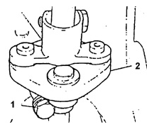
Steering Shaft Coupling.
1. CLAMP BOLT.
2. COUPLING ASSEMBLY.
Remove or disconnect
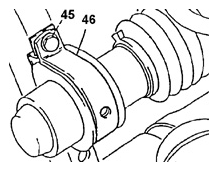
Rack and Pinion Steering Gear Mounting.
45. BOLT.
46. HOUSING MOUNTING BRACKET.
PROCEDURE.
1. Disconnect the negative battery cable.
2. Raise and properly support the vehicle.
3. Remove the two clamp bolts 1 from coupling 2 and slide the coupling up the steering column shaft. (Steered wheels must be in the straight-ahead position.)
4. Remove the air cleaner.
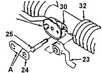
5. Remove both bolts 25 securing the inner ends of the tie rods to the rack. Before removing the bolts, bend back and remove locking plate 24, which secures the bolt heads.
bolts. Do not reuse plate 24..
6. Steering damper (if equipped)..
7. Both steering gear mounting clamps..
8. Remove dust boot 3 from the pinion shaft..
9. Remove the steering gear assembly through the right wheel well opening..
Warning.
If removed together with the steering gear mounting clamps.
bolts, install them and tighten to torque 20 N·m..
Install or connect

Tie Rod Ball Joint Attachment to Rack
23. TIE ROD (LH).
24. LOCKING PLATE.
25. BOLT.
26. SUPPORT PLATE.
29. TIE ROD (RH).
32. STEERING GEAR HOUSING BOOT

Tie Rod Removal (FOR VEHICLES WITH AUTOMATIC TRANSMISSION ONLY.
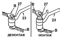
A. SLOT POSITION ON LOCKING PLATE DURING INSTALLATION.
B. WRENCH.
C. TO FACILITATE INSTALLATION, APPLY A THIN LAYER OF MULTI-PURPOSE GREASE TO THE BUSHING
(FOR VEHICLES WITH MANUAL TRANSMISSION ONLY.
23. TIE ROD (LH).
21. LOCKING PLATE.
25. BOLT.
26. SUPPORT PLATE (M/T MODELS ONLY).
27. TIE ROD BALL JOINT BUSHING.
30. WASHER.
32. HOUSING COVER.
33. STEERING DAMPER (FOR VEHICLES WITH AUTOMATIC TRANSMISSION ONLY)
PROCEDURE.
1. Install the steering gear assembly through the right wheel well opening..
2. Install dust boot 3 onto the pinion shaft..
3. Both steering gear bracket retaining clamps. (Only new self-locking nuts must be used.) Tighten the nuts and bolts of the steering gear bracket clamps.
to torque 35 N·m..
4. Steering damper (if removed from vehicle)..
5. Install two washers 30, which must be located between the guide
plate 10 and the inner ends of the tie rods..
6. Attach the inner ends of tie rods 23, 29 to the guide with bolts 25.
plate
10. Tighten the tie rod to steering rack mounting bolts.
to 90 N·m..
7. Install the locking plate onto support plate 26 and the heads of bolts 25
24. Slots on the locking plate must be positioned as shown in the illustration..
Tie Rod Removal..
8. Lower and install coupling 2 onto the end of the pinion shaft
5. Tighten the steering shaft coupling bolts to torque 25 N·m..
9. Air cleaner..
10. Lower the vehicle..
11. Connect the negative battery cable.
Test yourself
A quick Daewoo Nexia quiz: every answer comes with an explanation and a link to the manual page.