Steering Gear
Remove or disconnect:
PROCEDURE.
1. Steering gear assembly. Refer to illustration. Rack and pinion steering gear with hydraulic power assist.
2. Remove pinch bolt 1 from the coupling flange
2..
3. Remove coupling 2 from the valve shaft
10..
4. Remove dust cover 3 from the housing
55..
5. Remove locking plate 37 from the bolt heads
38. Discard the plate..
6. Bolts 38, support plate 39, steering tie rods 35 and
40..
7. Hose lines 56, 57 with O-rings
13..
8. Rubber bushing 50 and clamps 26, 42 of the protective boot (cut off).
9. Bushing 43 from the protective boot
44..
10. Protective boot 44 assembly with bushing 27 and washers 29 from the housing
55..
11. Guide plate
28..
12. Locknut 16 from the adjusting plug
17..
13. Adjusting plug 17 from the housing
55..
14. Spring 18 and plunger 14 with O-ring 15 from the housing
55..
15. Snap ring 4 from the housing
55..
16. Cap
24..
17. Holding the valve shaft stationary, unscrew nut 21 from the pinion shaft..
Warning.
Unscrewing nut 21 without holding the pinion shaft may cause damage.
teeth of the steering gear pinion..
18. Set the rack to the center position and mark its position on the housing.
marks on the valve shaft (to facilitate subsequent assembly)..
Warning.
Using a press, press on the threaded end of the pinion shaft and press it out.
the shaft neck out of bearing 22 to allow removal of the shaft.
pinion shaft assembly with valve body 10 from the housing
55..
19. Dust boot 5, inner seal 6, upper bearing 7 assembly,
valve body 10 with O-rings from the housing
8..
20. Cylinder 51 from housing 55 using wrench KM-
472. Before removal, mark the position of the hydraulic cylinder ports relative to the housing..
21. Rack 25 assembly with guide bushing 54 from the housing
55..
22. Unscrew nut 49 from the rod
25..
23. Remove piston 47 from rod 25 with O-rings 48 and 52, guide.
bushing 54 with O-rings 53 and 46, thrust washer
45..
24. Remove O-rings 53 and from guide bushing 54
46..
25. Snap ring 23 from the housing
55..
26. Bearing 22 assembly from the housing
55..
27. Seal 11 and upper bushing 12 of the pinion shaft from the housing
55..
Clean.
PROCEDURE.
1. Wash parts in clean power steering fluid..
2. Check that there are no foreign particles in the threaded holes of the housing..
3. Dry the parts..
Install or connect
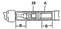
Centering the guide plate in the middle position A. WINDOW IN HOUSING.
B. EQUAL DISTANCES.
28. GUIDE PLATE
PROCEDURE.
1. Lubricate all seals with fresh power steering fluid..
2. Install upper bushing 12 of the pinion shaft into the housing bore
55..
3. Install pinion shaft seal 11 into housing 55 (using installer KM-108)..
4. Press bearing 22 into housing 55 (using a press)..
5. Install snap ring 23 into the housing groove
55..
Warning.
Mark the correct position of snap ring 23 before installation..
6. Assemble seals 46 and 48 with the guide bushing
54..
7. Assemble O-ring 53 and seal 52 with the piston
47..
8. Assemble thrust washer 45, rod guide bushing and piston assembly on the
rack rod
25..
9. Screw nut 49 onto the rod
25. Tighten the hydraulic cylinder rod nut to torque 30 N·m..
10. Install the rack assembly with piston and rod bushing into the housing..
11. Apply three drops of Loctite 242 or equivalent evenly around the circumference of the housing thread..
Warning.
Use a small amount of Loctite 242 or equivalent.
to allow easy unscrewing of hydraulic cylinder 51 from housing 55 for future repair.
repair..
12. Screw cylinder 51 onto the housing using wrench KM-
472..
Warning.
During installation, position the hydraulic cylinder ports as before.
relative to the housing (per the mark made earlier)..
13. Tighten hydraulic cylinder to torque 112 N·m..
14. Install guide plate 28 to the rack
25..
15. Set the rack with plate to the center position relative to the housing window.
16. Install valve body assembly with new O-rings 8 and snap ring 4.
into the housing
55..
Warning.
During installation, position the hydraulic cylinder ports as before.
relative to the housing (per the mark made earlier)..
17. After the valve body is fully installed in the housing, make sure.
the marks on the valve body shaft and housing align. Also check that guide plate 28 is in the center position..
18. Holding the valve body shaft from rotating, install nut
21. Tighten pinion shaft nut to torque 30 N·m..
Warning.
Tightening the nut without holding the pinion shaft from rotating may damage the steering gear pinion teeth..
19. Install cap 24 into the housing
55..
20. Install bearing 7 assembly onto the valve body shaft. Slide the bearing into place in the housing
55..
21. Install protective cap J-
34614..
22. Install seal 6 and dust boot 5 into the housing
55..
23. Install snap ring 4 into the housing groove
55..
24. Lubricate plunger 14 with O-ring 15, spring 18 and adjusting plug with lithium grease and install into the housing
55..
25. With the rack in the center position, turn clockwise.
adjusting plug 17 until it bottoms against the housing. Then back off the plug 30–40
degrees. Check the friction torque on the steering gear shaft..
Maximum friction torque from the spring preload
of the plunger must not exceed 1.8 N·m..
26. Screw locknut 16 onto the plug
17. Holding plug 17 from rotating, tighten.
the adjusting plug locknut to torque 70 N·m..
27. Remove bushing 27 from the boot
44..
28. Install new clamp 26 onto the boot
44..
29. Install bushing 27 into the boot
44..
30. To ease assembly, lightly lubricate bushing 27 and install it onto the housing
55..
31. Check that the washers 29 are correctly seated in the housing recesses.
44..
32. To ease assembly of the mechanism, insert one bolt 38 through washer 29 and
guide plate 28 and screw it into the rack.
25. This will secure the
correct position of the parts.
33. Install bushing 43 onto hydraulic cylinder 51 and into housing 44.
44..
34. Slide housing 44 along the gear housing so that bushing 27 seats in the mounting groove
on the gear housing.
55..
35. Install clamp 26 on housing 44.
44. Tighten the clamp using special tool KM-J-26610.
36. Install clamp 42 on bushing 43 of housing 44 so that the clamp connecting link
is positioned above the slot in the bushing. Tighten the clamp using special tool KM-J
26610..
Warning.
To ensure a tight connection, the clamp connecting link must be
positioned above the slot in the bushing.
37. Install pipes 56 and 57 with O-rings 13 to the valve body and
hydraulic cylinder. Tighten the fitting nuts on the valve body to 18 N·m, and the fitting nuts on the hydraulic cylinder to 28 N·m.
38. Insert bolts 38 into the holes of mounting plate 39, tie rod bushings 36, washers 29, and the holes of guide plate 28, and screw them into the rack.
25. Tighten the tie rod-to-rack mounting bolts to 90 N·m.
39. Install a new locking plate 37 onto the bolt heads.
38. During installation, check that the plate slots are correctly positioned.
40. Install the protective boot 3 onto the gear housing.
55..
41. Connect coupling 2 to the valve shaft end.
10..
42. Screw in coupling clamp bolt 1.
2..
43. Tighten the steering shaft coupling clamp bolt to 25 N·m.
44. Install the steering gear assembly on the vehicle.
Test yourself
A quick Daewoo Nexia quiz: every answer comes with an explanation and a link to the manual page.