Lever Switch, Steering Shaft, Steering Column (Non-Adjustable)
GENERAL INFORMATION
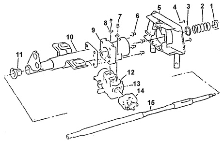
Steering column – standard equipment for vehicles with automatic transmission and manual transmission
1. NUT.
2. SPRING.
3. THRUST WASHER.
4. SCREW.
5. LEVER SWITCH MOUNTING HOUSING.
6. SHEAR BOLT.
7. SHEAR BOLT.
8. WASHER.
9. STEERING COLUMN UPPER HOUSING.
10. STEERING COLUMN COVER.
11. GUIDE BUSHING.
12. IGNITION LOCK MOUNTING HOUSING.
13. SETSCREW.
14. IGNITION SWITCH.
15. STEERING SHAFT
Remove or disconnect
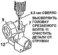
Shear Bolt Removal
7. SHEAR BOLT.
9. STEERING COLUMN UPPER HOUSING.
12. IGNITION LOCK MOUNTING HOUSING
PROCEDURE.
1. Steering wheel.
2. Steering column assembly.
3. Guide bushing 11 from the lower end of steering shaft 15, if it was not
removed previously.
4. Spring 2 from the upper end of the steering shaft.
15..
5. Thrust washer.
3..
6. Screws.
4..
7. Turn lever switch housing 5.
8. Turn the lock cylinder to the "RUN" position (ignition off).
9. Remove steering shaft 15 through the lower opening of the cover.
10..
10. Shear bolts 7, washers 8 and the ignition lock mounting housing.
10a. Drill out the heads of shear bolts 7 down to the steel washers.
8. Use a 6.5 mm drill bit, refer to Shear Bolt Removal illustration.
10b. Remove washers 8, separate housing 12 from the upper steering column housing 9. 10c. Unscrew the bolt shanks 7 from housing 12 using pliers.
Warning.
After drilling out the bolt heads, clean the parts of
metal chips.
11. Ignition lock cylinder from the housing.
12..
12. Unscrew the setscrew.
13..
13. Ignition switch 14 assembly.
14. Shear bolts 6 and the upper steering column housing.
14a. Drill out the heads of shear bolts 6 using an 8 mm drill bit.
14b. Separate upper housing 9 from the flange of steering column cover 10.
14c. Unscrew the bolt shanks 6 from housing 9 using pliers.
Warning.
After drilling out the bolt heads, clean the parts of
metal chips.
Install or connect

Ignition Switch Installation
12. IGNITION LOCK MOUNTING HOUSING.
13. SETSCREW.
14. IGNITION SWITCH
Warning.
All fasteners used in the operations described below must be
tightened securely before final tightening to the specified torque.
PROCEDURE.
1. Connect the upper housing 9 to the shroud flange 10 using shear bolts 6. Tighten the bolts and shear off the heads by applying a torque of approximately 15 N·m.
Warning.
To make sure the lock cylinder tang and the groove of ignition switch 14 align during installation, first turn them to the "RUN" position.
2. Install ignition switch 14 into the housing
12. Make sure the pin has engaged in the
hole of the switch lug.
14..
3. Install set screw 13 and tighten it by hand (torque approximately 0.3 N·m).
4. Install the ignition lock cylinder into the housing
12..
5. Attach housing 12 to the upper housing 9 of the steering column using washers 8 and
shear bolts.
7. Tighten the bolts and shear off the heads by applying a torque of
approximately 11 N·m.
6. Turn the ignition lock cylinder to the "RUN" position.
7. Insert steering shaft 15 into shroud 10 through the lower opening. Push the shaft in until it stops.
8. Turn the ignition lock cylinder to the "OFF-LOCK" position and remove the key.
9. Turn steering shaft 15 until the lock engages.
10. Install combination switch housing 5 onto the upper column housing 9. Install screws 4 and tighten them to a torque of 3.4 N·m.
11. Install guide bushing 11 onto the lower end of steering shaft 15 and into the shroud
10..
12. Install the steering column assembly into the vehicle.
Warning.
After connecting the steering shaft to the steering gear input shaft, remove
guide bushing 11 from shroud 10 and leave it on steering shaft 15 for
future use.
13. Install thrust washer 3 and the spring onto the upper end of the shaft
15..
14. Install the steering wheel onto the shaft
15. Install nut 1 and tighten it to a torque of 17 N·m.
Test yourself
A quick Daewoo Nexia quiz: every answer comes with an explanation and a link to the manual page.