Removing and installing the drive shaft
If the bellows are collapsed, the drive shaft does not need to be removed. Remove the small clamp. Lift the bellows with a screwdriver to bleed air. Then secure the bellows with a new clamp.
RemovalEngage a gear and apply the parking brake.
Remove the wheel cover.
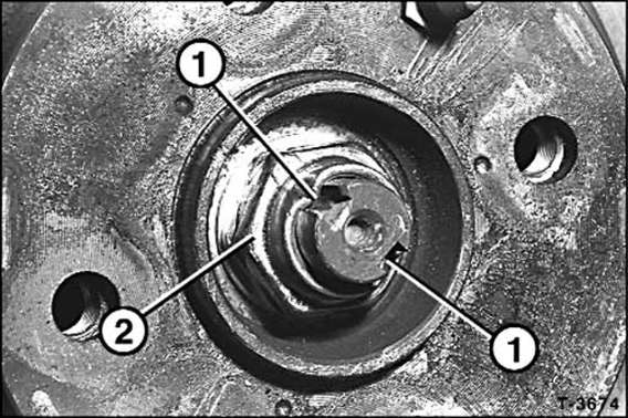
Bend back lock - 1 - and loosen the hub nut - 2 -, SW32. Caution: the nut is tightened to a high torque; the vehicle must stand on the ground during this work! Otherwise there is a risk of accident!
Disconnect the battery negative (-) cable. Warning: this erases electronic memories, such as engine operating values. Observe the notes in the chapter "Remove and install battery".
Mark the position of the front wheels relative to the wheel hub with paint.
This allows the balanced wheel to be refitted in the same position. Loosen the wheel bolts. The vehicle must be standing on the ground.
Raise the vehicle at the front and remove the front wheels.
Press the tie rod end out of the steering knuckle, see page 162.

Unbolt the steering knuckle from the strut.
Tie the drive shaft up with wire so the joints are not bent to the stop when one side is removed.
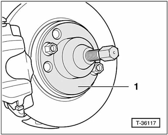
Pull the drive shaft out of the front wheel hub by hand by pulling the steering knuckle outward.
If this is not possible, press the drive shaft out with a commercially available hub puller - 1 -.
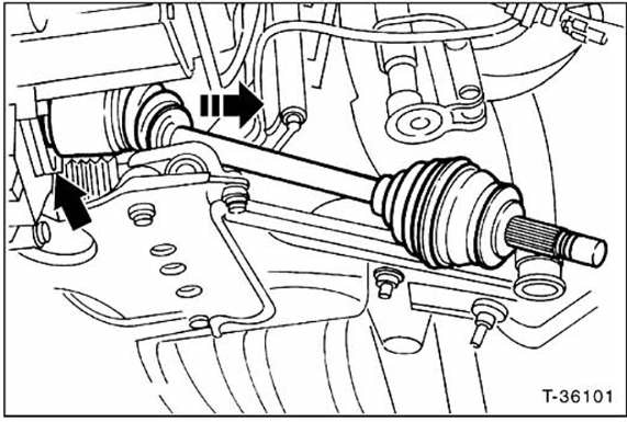
1.4 L engine: pull the drive shaft out of the differential by levering lightly at the insertion point and set it aside.
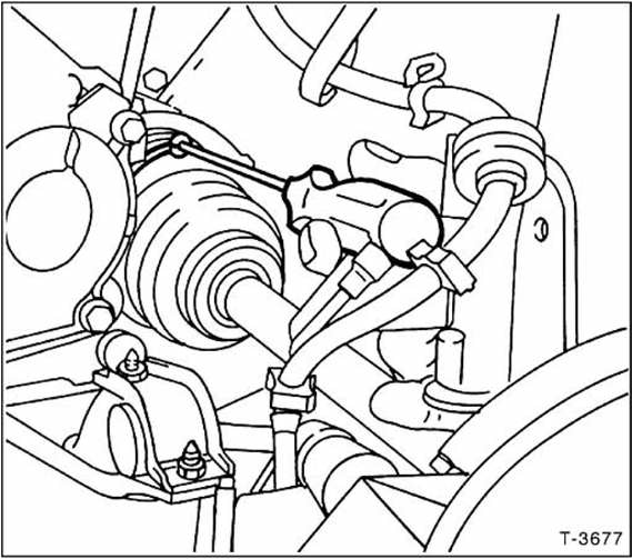
1.6 L engine: release the large-diameter retaining band on the inner joint and pull out the tripod joint.
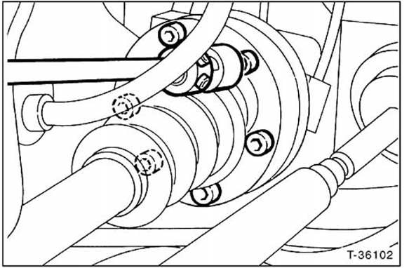
1.8/2.0 L engine: unbolt the inner joint of the left drive shaft from the transmission flange. Unbolt the inner joint of the right drive shaft from the flange of the intermediate shaft.
Remove the drive shaft.
Before installation, clean the splines of the drive shaft and wheel hub with petrol (free of grease and oil) and remove all residue.
Insert the drive shaft into the transmission.
1.8/2.0 L engine: tighten the inner joint to the 40 N·m bolts.
Insert the drive shaft into the splines of the front wheel hub.
Clean the threaded shank of the axle shaft with a wire brush and dry it with compressed air.
Fit a new washer and screw a new axle nut onto the drive shaft hand-tight; do not tighten yet.
Bolt the steering knuckle to the strut, see page 140.
Insert the tie rod end into the steering arm and bolt it on with a new self-locking nut, see page 162.
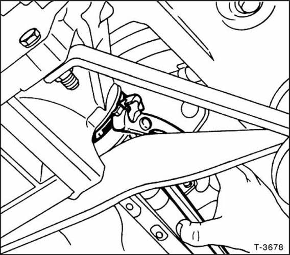
1.6 L engine: tighten the large-diameter retaining band on the inner joint.
Position the front wheels so that the marks made during removal line up. Before fitting, lightly grease the centering seat of the rim on the wheel hub and the conical surface of the wheel bolts with wheel bearing grease. Do not grease or oil the threads of the wheel bolts. Fit the wheels.
Lower the vehicle and tighten the wheel bolts crosswise to 90 N·m.
Unscrew the axle nut of the drive shaft. Clean the threads of the nut and shaft with methylated spirits.
Apply locking compound, for example Loctite 270, to the entire thread of the shaft.
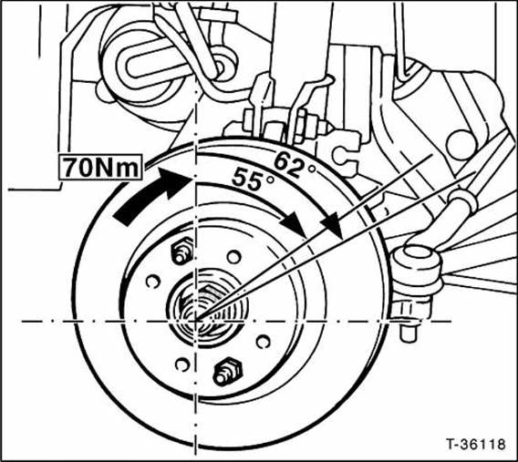
Tighten the hub nut to 70 N·m with a torque wrench. Then tighten the nut a further angle using a rigid wrench.


Stake the axle nut (hub nut) at the edge opposite the tightening direction with a chisel - 1 -, see illustration.
Install the wheel cover.
Connect the battery negative cable (-).
Set the clock.
If required, enter the radio anti-theft code.
Test yourself
A quick Fiat Bravo quiz: every answer comes with an explanation and a link to the manual page.