Disassembling driveshaft
Replace defective boots immediately. To replace the boots, the driveshaft must be disassembled. If dirt has entered the grease, wash out the joint and lubricate it with new Tutela MRM2 grease from Fiat (lithium-MoS2 grease). Defective balls or raceways in the bearings cause load-change knocking and clicking noises. In this case, replace the joints completely.
This description applies to models with 1.4 L, 1.6 L and 1.9 L engines. Differences for the 1.8 L and 2.0 L engines are listed at the end of the chapter.
If the splined shaft and/or the outer CV joint is replaced, be sure to observe the same color code.
A splined shaft with a blue color code matches CV joints with a blue or white color code. A splined shaft with a red color code matches CV joints with a red or white color code.
Caution: with the driveshaft removed, do not push the vehicle. Without axial preload, the rolling elements of the wheel bearing will be damaged. DisassemblyRemove the driveshaft and clamp it in a vise.
Mark the installation position of the boots with a felt-tip pen.
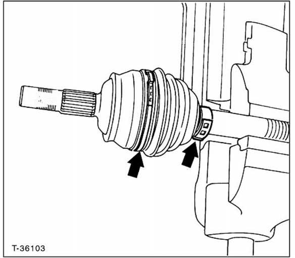
Cut open the hose clamp on the outer CV boot with side cutters and remove it. Push the CV boot back.

Wipe off the grease, spread the circlip with snap ring pliers and pull the driveshaft out of the joint flange.
Make sure the balls cannot slip out of the joint.
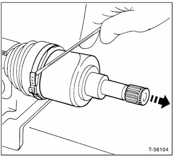
1.4 L engine: open the hose clamp on the inner tripod joint and pull off the joint housing.
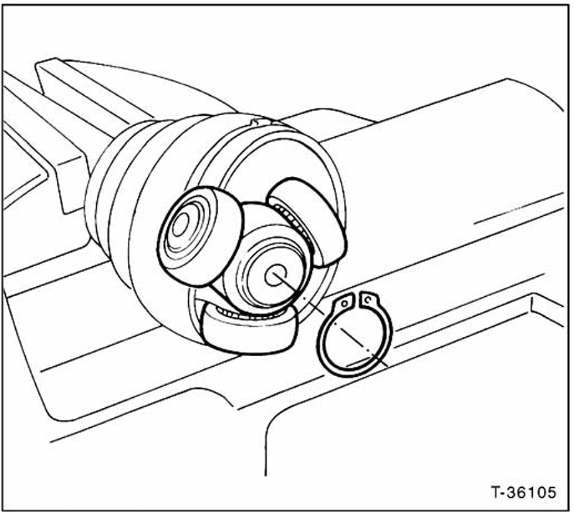
Pull off the inner tripod joint. First spread the circlip with suitable pliers and remove it. Mark the installation position of the joint with a felt-tip pen. A suitable puller may be required for removal.
Cut open the hose clamps at the small diameter of the boots with side cutters and remove them.
Remove the rubber boots.
Mark the installation position of the sealed bearing and pull the bearing off with a commercially available two-arm puller, see also illustration T-3671 on page 145.
Mark the installation position of the balancer weight and unscrew it, see also illustration T-3671 on page 145.
Wash the CV joints thoroughly with gasoline and visually inspect them for proper condition. Balls and raceways must be mirror-smooth and must not show running marks or grooves. Replace a defective joint.
Visually inspect the driveshaft. The shaft must not be bent or show runout. The contact surfaces of the boots must not be worn.
Always replace the CV boots.
Lightly grease the driveshaft surface so the boot slides on more easily.
Slide the new CV boot with hose clamp for the outer joint onto the shaft.
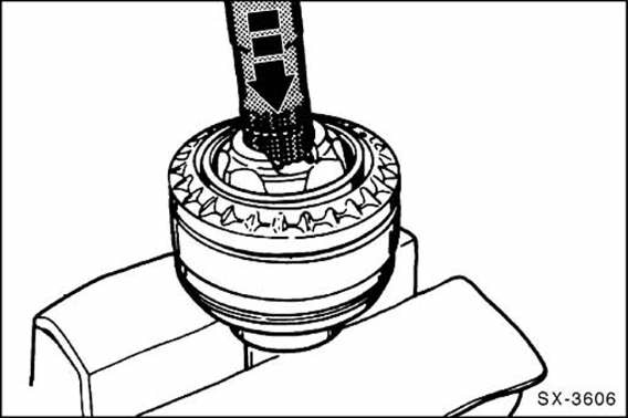
Press the shaft with a new circlip straight into the joint's splines until the circlip engages.
Fill the outer joint with Tutela MRM2 grease, half on each side. If only the CV boot is replaced, re-grease the joint only if necessary.
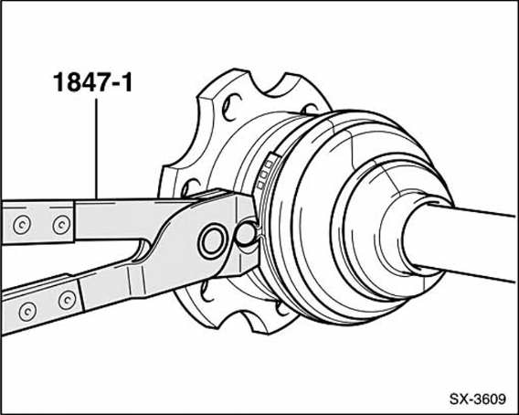
Position the CV boot correctly and tighten the hose clamps with pliers, for example Hazet 1847-1.
Slide the new rubber boot for the inner joint onto the shaft with its retaining band at the small diameter.
If removed, fit the balancer weight according to the mark made and tighten it with 10 N·m, see also illustration T-3671 on page 145.
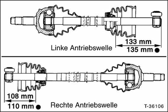
1.6 L / 1.9 L engine: press the sealed bearing on to the correct position, see illustration. = Alternative dimension.
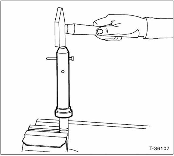
Press the sealed bearing on with a driving tube. The Fiat driving mandrel already has the holes for the stop pin at the correct spacing, see illustration.
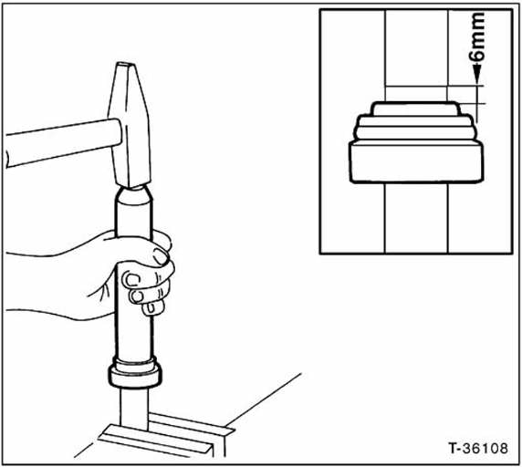
Caution: if a sealed bearing of the "Nardella" type is installed, check the correct installation position, see detail illustration.
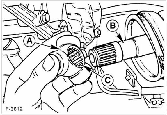
Inner joint: slide the tripod - a - onto the driveshaft - b - and secure it with a new circlip. Observe the mark made during removal.
If necessary, press the tripod star onto the shaft with a suitable tube until it stops. Caution: do not damage the bearing seat of the rollers. C - internal splines in the tripod star.
Position the rubber boot correctly and secure it with the retaining band at the small diameter.
1.4 L engine: secure the boot to the joint housing with a hose clamp.
Install the driveshaft.
Cut through the retaining bands of the inner CV joint.
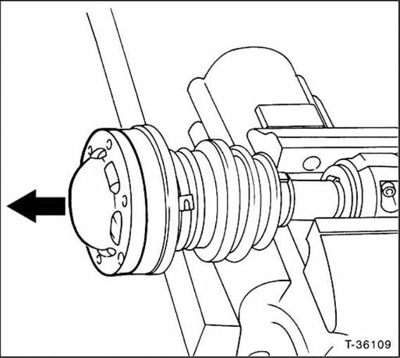
Drive the protective cap off the inner joint.
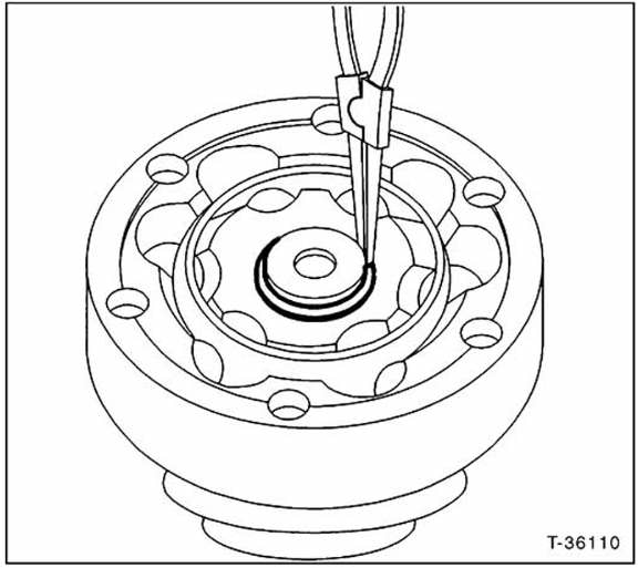
Remove the inner CV joint. To do so, spread the circlip with snap ring pliers and pull the joint off the shaft.
Pull the rubber boot, retaining bands and spring washer off the driveshaft.
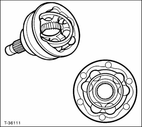
Wash the CV joints thoroughly with gasoline or diesel and visually inspect them for proper condition. Balls and raceways must be mirror-smooth and must not show running marks or grooves. Replace a defective joint.
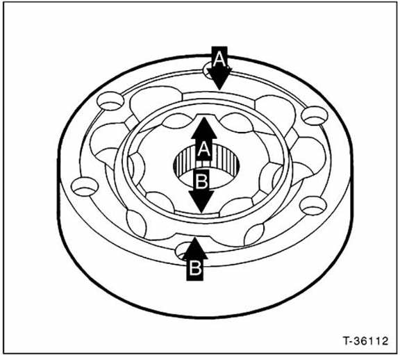
Caution: if the balls fall out when removing the joints, observe the markings shown for installation. - A - must be matched with - a - and - b - with - b -, otherwise the joint will bind.
Test yourself
A quick Fiat Bravo quiz: every answer comes with an explanation and a link to the manual page.