VTEC System - Valve Lash Adjusters, Synchronizing Assemblies
Valve Lash Adjusters
PROCEDURE
1. The four valve lash adjusters are installed in special bores in each cylinder head. The rocker arm assemblies must be removed to gain access to the lash adjusters (see Rocker Arm Assembly Removal, Inspection and Installation).
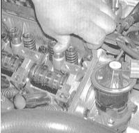
2. Check the operation of the lash adjusters by pressing the plungers with your finger. The plunger should move with slight resistance that gradually increases as it is depressed. If not, replace the defective assembly.
Synchronizing Assemblies
PROCEDURE
1. After removing and disassembling the rocker arm assemblies (see Rocker Arm Assembly Removal, Inspection and Installation), also remove the synchronizing components. Disassemble the assemblies into their individual components.
VTEC synchronizing assembly components:
a) Primary valve rocker arm (primary rocker arm);
b) Secondary valve rocker arm (secondary rocker arm);
c) Intermediate rocker arm;
d) Synchronizing piston A;
e) Synchronizing piston B;
f) Return piston.
2. Check the condition of the return spring. Make sure it is not broken or collapsed. Replace if necessary.
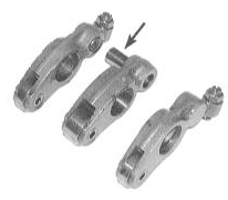
3. Check all other components (rocker arms and synchronizing pistons) for wear, scoring, galling, signs of overheating and other damage. Check that the pistons move freely by hand. Replace any defective parts.
4. Assembly is performed in the reverse order of disassembly.
Assemble the components of each cylinder's assembly together, secure them with a rubber band, and only then install them on the shaft (see Rocker Arm Assembly Removal, Inspection and Installation).
Test yourself
A quick Honda Accord quiz: every answer comes with an explanation and a link to the manual page.