ETC System (Electronic Throttle Control)
Specifications
SPECIFICATIONS
sensor
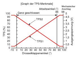
| Position | Opening Percentage (%) | Output Voltage (V) [Vref = 5 V] | |
| TP1 | Idle | 8,5~11,5 | 0,43~0,58 |
| THW | 88~96 | 4,40~4,80 | |
| TP2 | Idle | 88,5~91,5 | 4,43~4,58 |
| THW | 2~10 | 0,10~0,50 | |
| Limp Home Control | Throttle Stuck at 5° | ||
| Supply Voltage (V) | 4,8 - 5,2 | ||
| Type | Non-Contact Hall IC Sensor [built into ETC module] | ||
ENGINE
| Position | SPECIFICATIONS |
| Coil Resistance (Ω) | 0,3 ~ 100 [20 °C] |
| Maximum Allowable Current (A) | < 10,0 |
| Type | DC Motor [Built into ETC Module] |
Description and Operation
Description
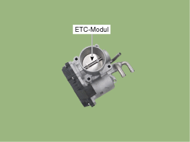
Electronic Throttle Control (ETC) consists of a throttle body with a built-in control motor and a throttle position sensor (TPS). Instead of a conventional accelerator cable, the accelerator pedal sensor (APS) is used to detect the driver's input. The ECM uses the APS signal to calculate the desired throttle angle; the throttle position is then controlled by the ETC motor via the ECM. The TPS signal is used to send throttle position information to the ECM. Electronic throttle control provides precise control of throttle position; external cruise control modules and cables are not required.
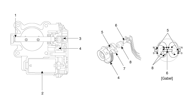
| 1. Bearing 2. DC Motor 3. Non-Contact Hall Sensor 4. Gear |
5. Magnet 6. Hall IC 7. Connector 8. Stator |
CIRCUIT DIAGRAM
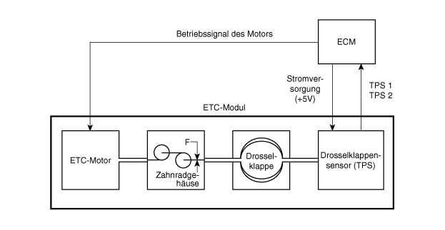
Schematic diagrams
Circuit diagram
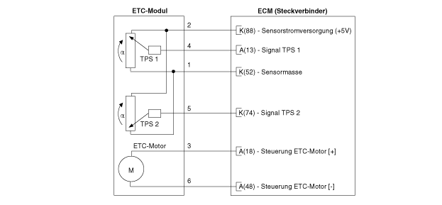
repair procedures
TEST
THROTTLE POSITION SENSOR (TPS)
Connect the KDS to the Data Link Connector (DLC).
Start the engine and measure the output voltage of APS 1 and 2 at idle and at full throttle opening.
Position Opening Percentage (%) Output Voltage (V) [Vref = 5 V] TP1 Idle 8,5~11,5 0,43~0,58 THW 88~96 4,40~4,80 TP2 Idle 88,5~91,5 4,43~4,58 THW 2~10 0,10~0,50
ETC motor
Turn the ignition off.
Disconnect the ETC module connector.
Measure the resistance between terminals 1 and 2 of the ETC module.
Make sure the resistance is within specification.
Specification: 0.3–100 Ω [20 °C]
expansion
Turn the ignition switch OFF and disconnect the negative (-) battery terminal.
Remove the air filter.
(Refer to Engine Mechanical - "Air Cleaner").
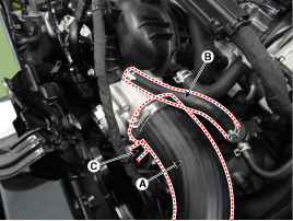
Disconnect the air intake hose (A), vapor hose (B), and ETC module connector (C).
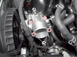
Remove the mounting screws (A) of the ETC module.
ETC module mounting bolt:
9,8~11.8 N·m
Disconnect the coolant hoses (B), then remove the ETC module (A).
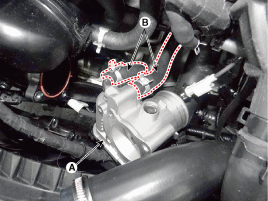
CLEANING
Remove the ETC module.
(Refer to Engine Control - "ETC System")
Hold the ETC module plate (A) open.
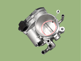
Wipe dirt from the throttle body with a damp, soft cloth.
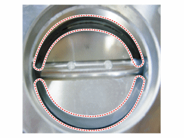
After cleaning, reinstall the ETC module, then perform the ETC programming.
(Refer to Engine Control - "ETC System" - Adjustment)
Installation
Installation is the reverse of removal.
INSPECTION
ETC Module Programming Procedure
After replacing or reinstalling the ETC module, make sure reprogramming is performed.
With the ignition on, wait 1 minute.
After starting, let the engine idle for 15 minutes.
Wait 1 minute with the ignition switched OFF.
Restart the engine and check idle stability.
Troubleshooting
FAIL-SAFE MODE
| Position | Limp Home Control | |
| ETC motor | Throttle Stuck at 5° | |
| TPS | TPS 1 Fault | ECM Checks TPS2 |
| TPS 2 Fault | ECM Checks TPS1 | |
| TPS 1.2 Fault | Throttle Stuck at 5° | |
| APS | APS 1 Malfunction | ECM Checks APS2 |
| APS 2 Malfunction | ECM Checks APS1 | |
| APS 1.2 Fault | Idle | |
Test yourself
A quick Kia Stonic quiz: every answer comes with an explanation and a link to the manual page.