Motorsteuermodul (ECM)
Schematische darstellungen
ECM-Klemme und Eingangs-/Ausgangssignal
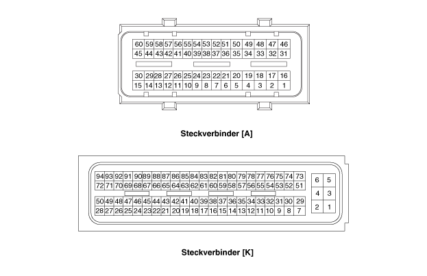
ECM-KLEMMENBESCHREIBUNG
| Individual Components | PIN Code | Beschreibung |
| BATTERY | K-7 | Battery power (B+) |
| K-4 | Battery power (B+) | |
| Relay | K-51 | Battery power (B+) |
| K-6 | Battery power (B+) | |
| K-5 | HAUPTRELAIS STEUERAUSGANG | |
| BODY GROUND | K-1 | ECM ground |
| K-2 | ECM ground | |
| K-3 | ECM ground | |
| Ignition coil | K-11 | Zündspule (Zylinder № 1, № 2, № 3) Rückmeldesignal |
| A-17 | Steuerungsausgang Zündspule (Zylinder № 1) | |
| A-2 | Steuerungsausgang Zündspule (Zylinder № 2) | |
| A-1 | Steuerungsausgang Zündspule (Zylinder № 3) | |
| RAIL-DRUCKSENSOR (RPS) | K-87 | RPS Power Supply (+5V) |
| K-78 | RPS Signal Input | |
| K-36 | RPS ground | |
| INJECTOR | A-34 | Steuerungsausgang Injektor (Zylinder Nr. 1) [NIEDRIG] |
| A-47 | Steuerungsausgang Injektor (Zylinder Nr. 1) [HOCH] | |
| A-20 | Steuerungsausgang Injektor (Zylinder Nr. 2) [NIEDRIG] | |
| A-31 | Steuerungsausgang Injektor (Zylinder Nr. 2) [HOCH] | |
| A-5 | Steuerungsausgang Injektor (Zylinder Nr. 3) [NIEDRIG] | |
| A-32 | Steuerungsausgang Injektor (Zylinder Nr. 3) [HOCH] | |
| NOCKENWELLENSENSOR (CMPS) | K-44 | CMPS [Bank 1 / Intake and Exhaust] Power Supply (+5 V) |
| A-56 | CMPS Signal Input [Bank 1 / Intake] | |
| A-36 | CMPS [Bank 1 / Intake] Ground | |
| A-24 | CMPS Eingangssignal [Reihe 1/Auslass] | |
| A-37 | CMPS [Bank 1 / Exhaust] Ground | |
| Elektrischer WGT-Stellantrieb (EWGA) | A-4 | EWGA-Motorsteuerung (-) |
| A-19 | EWGA-Motorsteuerung (-) | |
| K-86 | EWGA Sensor Power Supply (+5 V) | |
| A-12 | Eingangssignal EWGA-Sensorrückmeldung | |
| K-12 | EWGA Sensor Ground | |
| ACCELERATOR PEDAL POSITION SENSOR (APS) | K-30 | APS2 Sensor Ground |
| K-77 | APS Signaleingang 2 | |
| K-43 | APS 2 Power Supply (+5 V) | |
| K-8 | APS 1 Ground | |
| A-14 | APS 1 Signal | |
| K-66 | APS 1 Power Supply (+5 V) | |
| Alternator | K-61 | LIN Communication Input / Output Signal (COM) |
| KRAFTSTOFFPUMPENRELAIS | K-71 | Steuerausgang Kraftstoffpumpenrelais (Ohne Ausführung mit Wegfahrsperre) |
| K-27 | Steuerausgang Kraftstoffpumpenrelais (Mit Ausführung mit Wegfahrsperre) | |
| Heated Oxygen Sensor (HO2S) | K-60 | HO2S [Bank 1 / Sensor 1] Rc (Compensation Resistor) Signal |
| K-81 | HO2S [Bank 1 / Sensor 1] Rc/Rp (Pump Cell Current) Signal | |
| K-80 | HO2S [Bank 1 / Sensor 1] VS-/IP- (Common Ground for VS, IP) Signal | |
| K-59 | HO2S [Bank 1 / Sensor 1] VS+ (Nernst Cell Voltage) Signal | |
| K-89 | HO2S [Reihe 1/Sonde 1] Heizungsausgang | |
| A-41 | HO2S [Bank 1 / Sensor 2] Signal | |
| A-57 | HO2S [Bank 1 / Sensor 2] Ground | |
| K-91 | Steuerungsausgang Sondenheizung [Reihe 1 / Sonde 2] | |
| LADDRUCKSENSOR (BPS) | K-10 | BARO Sensor Ground |
| K-87 | BARO Power Supply (+5 V) | |
| A-9 | BPS Signaleingang | |
| Intake Manifold Absolute Pressure Sensor (MAP) and Intake Air Temperature Sensor (IAT) |
K-9 | MAP and IAT Sensors |
| K-56 | IAT Signal Input | |
| K-86 | MAP Power Supply (+5 V) | |
| K-57 | MAP Signal Input | |
| CVVT Oil Control Valve (OCV) | K-22 | OCV Steuerungsausgang [Reihe 1 / Einlass] |
| K-50 | OCV Steuerungsausgang [Reihe 1/Auslass] | |
| Knock Sensor (KS) | K-79 | KS-Eingangssignal |
| C-58 | Ground KS (Knock Sensor) mass | |
| Kraftstoffdruckregelventil (FPCV) | A-35 | FPCV control output [High] |
| A-50 | FPCV control output [Low] | |
| ENGINE COOLANT TEMPERATURE SENSOR (ECTS) | C-16 | ECTS ground |
| A-7 | ECTS signal | |
| Steuermagnetventil des Kühlmitteltemperatursensors (ECTS) | C-93 | Steuerausgang ECTS-Steuermagnetventil |
| RCV control solenoid valve (RCV valve) | C-68 | RCV valve control output |
| Starter relay | C-67 | Starter relay control output (High) |
| C-41 | Starter relay control output (Low) | |
| C-41 | Starter relay control output (Low) | |
| CRANKSHAFT POSITION SENSOR (CKPS) | A-53 | CKPS signal [With ISG] |
| A-54 | Eingangssignal CKPS [Mit ISG] | |
| C-65 | CKPS power supply (+5V) [With ISG] | |
| A-54 | Eingangssignal CKPS [Ohne ISG] | |
| C-53 | CKPS ground [Without ISG] | |
| Bremskraftverstärker-Unterdrucksensor (BBVPS) | A-15 | BBVPS signal |
| C-35 | BBVPS ground | |
| C-65 | BBVPS power supply (+5V) | |
| ISG OFF switch | C-46 | Ausgangssignal Kontrollleuchte des ISG-OFF-Schalters |
| A-44 | Masse ISG-OFF-Schalter | |
| Neutral Switch | A-22 | Neutral switch input signal (Ground) |
| Ignition switch | A-27 | Ignition switch input signal (or push-button switch) |
| Zündschlossschalter | A-60 | Ignition lock switch input signal (Ground) |
| Neutral Switch | A-22 | Neutral switch input signal (Ground) |
| Kühlmittelstoppmagnetventil (CSV) | C-49 | CSV-Steuerausgang |
| Other control module | C-82 | Engine speed output signal (rpm) |
| SPÜLMAGNETVENTIL (PCSV) | C-94 | PCSV-Steuerausgang |
| Electronic Throttle Control (ETC) module | A-13 | TPS 1 Signalingang |
| C-52 | TPS 1 and 2 ground | |
| C-74 | TPS 2 signal | |
| C-88 | TPS 1 and 2 power supply (+5 V) | |
| A-18 | Steuerausgang ETC-Motor [-] [Mit ISG / AMS] | |
| A-48 | Steuerausgang ETC-Motor [-] [Mit ISG / AMS] | |
| A/C compressor relay | C-20 | Ausgangssignal Klimakompressor-Relaissteuerung [Mit ISG / AMS] |
| Battery Sensor | K-61 | LIN communication input signal [With ISG / AMS] |
| Windshield wiper switch | A-21 | Eingangssignal Wischerschalter [Mit ISG / AMS] |
| Blower switch | C-53 | Max. blower switch input signal [With ISG / AMS] |
| DEF | A-45 | Eingangssignal für elektrische Last des Enteisers [Mit ISG / AMS] |
| Wiper switch | A-23 | Eingangssignal für elektrische Last der Scheinwerfer [Mit ISG / AMS] |
| Instrument cluster | C-17 | Steuerausgang LED-Lampe Tankdeckel offen |
| Servolenkungsschalter | A-6 | Eingangssignal für elektrische Last des Servolenkungsschalters [Ohne MDPS] |
| Brake switch | A-28 | Signaleingang Bremsschalter |
| A-29 | Signaleingang Bremslichtschalter | |
| Kupplungsschalter | A-30 | Kupplungsschalter Signaleingang |
| Vehicle Speed Sensor (VSS) | A-51 | Signaleingang Fahrzeug-Geschwindigkeitssensor |
| A-52 | Masse Fahrzeuggeschwindigkeitssensor | |
| A/C Pressure Transducer (APT) | C-37 | ATP GROUND |
| C-54 | APT signal | |
| K-87 | APS Power Supply (+5V) | |
| Cooling Fan Relay | K-24 | Steuerungsausgang Kühllüfterrelais [PWM] [Mit Kühllüftersteuermodul] |
| C-CAN: Other Control Modules, Diagnostic Tester (DLC: Multi-Purpose Check Connector (MPCC) |
K-84 | C-CAN 2 [High] |
| K-62 | C-CAN 2 [Low] | |
| K-85 | C-CAN [High] | |
| K-63 | C-CAN [Low] |
Repair Procedures
Removal
Zündung ausschalten und Minuskabel (-) der Batterie abklemmen.
Battery
(Refer to Engine Electrical - "Battery")
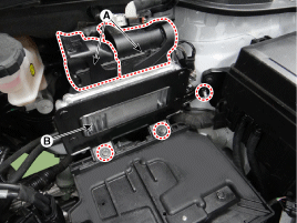
ECM-Stecker (A) abziehen.
Befestigungsschrauben und -mutter entfernen und ECM-Halterung (B) ausbauen.
Befestigungsschraube/-mutter ECM-Halterung: 9,8 ~ 11.8 N·m
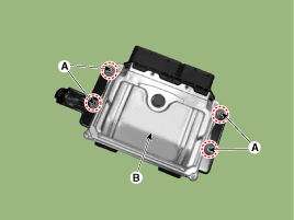
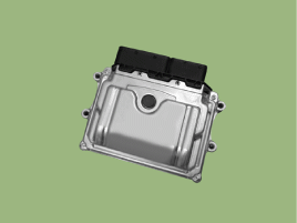
Befestigungsmuttern (A) lösen und ECM (B) aus der Halterung nehmen.
ECM-Befestigungsmutter: 9,8 ~ 11.8 N·m
Installation
Der Einbau erfolgt in der umgekehrten Reihenfolge des Ausbaus.
PRÜFVERFAHREN BEI ECM-FEHLFUNKTION
ECM GROUND CIRCUIT INSPECTION: Measure the resistance between the ECM and body ground, using the rear of the ECM harness connector as the side ECM probe point. Repair any problems found.
Specification: 1 Ω max.
ECM CONNECTOR INSPECTION: Disconnect the ECM connector. Visually inspect the ground terminals on the ECM side and the harness side for bent terminals or poor contact. Repair any problems found.
If the problem cannot be found in Steps 1 and 2, the ECM may be faulty. If so, make sure there are no DTCs before replacing the ECM with a new one. Recheck the vehicle. If a DTC is found, it must be diagnosed before replacing the ECM.
ORIGINAL ECM RECHECK: Install the original ECM (may be faulty) in a verified good vehicle and recheck the vehicle. If the problem recurs, replace the ECM. If the problem does not recur, the fault is intermittent. (Refer to "Intermittent Malfunction Procedure" under General Inspection Procedures.)
INSTALLATION
ECM Neutralmodusverfahren
Nachdem das ECM des Fahrzeugs mit Wegfahrsperre ersetzt wurde, muss folgendes Verfahren durchgeführt werden.
[Bei Einbau eines gebrauchten ECM] |
Den Vorgang "ECM Neutralmodus" mit dem KDS durchführen.
(Siehe Karosserieelektrik - "Wegfahrsperrensystem - Reparaturverfahren")
After ECM Neutral Mode ends, perform "Key Learning" with the KDS.
(Siehe Karosserieelektrik - "Wegfahrsperrensystem - Reparaturverfahren")
[Bei Einbau eines neuen ECM] Perform "Key Learning" using the KDS. (Siehe Karosserieelektrik - "Wegfahrsperrensystem - Reparaturverfahren") |
Nachdem das ECM des Fahrzeugs mit Smartkey-System (Motorstartknopf) ersetzt wurde, muss folgendes Verfahren durchgeführt werden.
[Bei Einbau eines gebrauchten ECM] |
Den Vorgang "ECM Neutralmodus" mit dem KDS durchführen.
(Siehe "Karosserieelektrik" - "Smartkey - Reparaturverfahren")
After ECM Neutral Mode ends, turn the ignition on and then off with the Smart Key or Start button. The Smart Key data will then be transmitted automatically to the ECM.
[Bei Einbau eines neuen ECM] Turn the ignition on and then off using the Smart Key or Start button. Smart Key data is transmitted automatically to the ECM. |
ETC Module Programming
Nach dem Austausch des ETC-Moduls ist eine Neuprogrammierung erforderlich.
(Siehe Elektronische Drosselklappensteuerung - "Einstellung")
Test yourself
A quick Kia Stonic quiz: every answer comes with an explanation and a link to the manual page.