Piston and Connecting Rod Assembly - Inspection
GENERAL INFORMATION
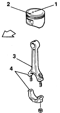
Correct Relative Orientation of Piston and Connecting Rod
1. Piston size group number
2. Orientation mark
3. Lubrication hole in connecting rod body
4. Location of cylinder number stamped on connecting rod
Inspection
PROCEDURE
1. Before inspection, clean the connecting rods and pistons and remove the old rings from the pistons.
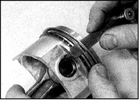
2. Carefully spread the ring and slide it toward the top of the piston. To prevent the ring from dropping into an empty groove during removal, insert two or three old feeler gauges under the ring.
3. Scrape carbon from the piston crowns. After removing the heavy outer layer of carbon, clean the piston crown by hand with a wire brush (or emery cloth on a cloth backing).
4. Carefully remove carbon from the piston ring grooves using a broken old piston ring.
5. Wash the piston and connecting rod assembly in solvent and dry thoroughly. Make sure the oil drain slots in the ring grooves are clean.
6. Measure the piston diameter with a micrometer perpendicular to the piston pin axis (at the specified distance from the edge of the piston skirt) and compare the result with the specifications. The piston size group is stamped on the piston crown. If piston wear exceeds the service limit, replace the piston.
7. Check the piston ring side clearance. To do this, insert the ring into its groove from the outside and measure the clearance between the upper surface of the ring and the groove wall with a feeler gauge. If the clearance exceeds the specification even with a new ring, replace the piston.
8. Check the piston ring end gap. Insert the ring into the corresponding cylinder and push it in with the piston crown to keep the ring square in the bore. Push the ring in to the depth where the edge of the piston skirt is level with the cylinder block mating surface, then remove the piston. Measure the gap with a feeler gauge. If the gap exceeds the specification, replace the rings and repeat the procedure. If the gap still exceeds the specification with new rings, the cylinder must be bored and honed (refer to subsection 3.1.2.10).
9. Carefully check the piston skirt, piston pin bosses, and the areas between the piston ring grooves for cracks.
10. Check the piston skirt friction area for chips and scoring, and the edges of the crown for burn marks. Chips and scoring indicate frequent engine overheating, one possible cause of which may be abnormal fuel combustion. In this case, thoroughly check the fuel, lubrication, and cooling systems. Melting marks on the side surface of the piston indicate combustion gas leakage from the combustion chamber. Burn-through of the piston crown or burnt areas at the crown edges indicate abnormal engine operation due to incorrect ignition timing (ignition advanced too early) or detonation. If these defects are found, determine and eliminate their cause; otherwise, the causes of this wear may continue to act. Causes of abnormal engine operation may include air leaks in the intake manifold, incorrect ignition timing, or a fuel injection system malfunction.
11. Pitting corrosion of the piston in the form of small pits indicates that coolant has entered the combustion chamber (and the crankcase). Again, determine the cause and eliminate it.
12. Carefully check the connecting rods for damage such as cracks near the small end and at the bearing mounting areas. Check the connecting rod body for distortion (twisting or bending). Connecting rod damage is unlikely and occurs only in cases of engine seizure or severe overheating. A thorough connecting rod inspection can only be performed in a workshop with the required equipment.
13. If necessary, remove the piston from the connecting rod and reassemble it as follows.

14. Remove the piston pin circlips and push out the piston pin. If necessary, support the piston and carefully drive out the pin by tapping it with a hammer and a drift.
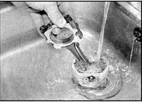
15. Removing the piston pin is much easier if the piston is heated to 60–70°C.
16. Check the piston pin and the connecting rod small end bore for signs of wear or damage. Check the piston pin clearance in the piston and in the connecting rod.
17. If the connecting rod small end bushing and piston pin are severely worn, or if the pin clearance in the connecting rod small end exceeds the specification, replace the pin and bushing. Connecting rod small end bushing replacement must be performed at a workshop.
18. If the piston-to-pin clearance greatly exceeds the specification, replace the piston and pin as a set. Note that the piston-to-pin clearance is not as critical as the clearance in the connecting rod small end.
19. Connecting rods generally do not need to be replaced, except in cases of engine seizure or other serious damage. Check the connecting rods visually. If distortion is found, take them to an automotive service workshop for inspection and repair.
20. Purchase new parts to replace the worn ones.
21. Orient the piston and connecting rod so that the mark on the piston (arrow or line) that must face the front of the engine is correctly positioned relative to the oil hole in the connecting rod body (see illustration Correct Piston and Connecting Rod Orientation). With correct orientation, the mark on the piston must face the front of the engine, and the oil hole in the connecting rod body must face the rear of the cylinder block.
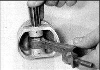
22. Lightly lubricate the piston pin with fresh engine oil and insert it into the holes in the piston and the connecting rod small end. If necessary, tap the pin into place with a hammer and a drift.
Warning: To make it easier to install the piston pin, heat the piston.
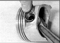
23. Check that the pin rotates freely in the piston bosses, then install the retaining rings into the piston grooves.
Test yourself
A quick Nissan Sunny quiz: every answer comes with an explanation and a link to the manual page.