Data Signal Circuit between Radio Receiver and Stereo Jack Adapter. Diagnostic Trouble Code Chart. Display does not Dim when Light Control Switch is Turned ON
Data Signal Circuit between Radio Receiver and Stereo Jack Adapter
DESCRIPTION
The stereo jack adapter assembly sends the sound data signal or image data signal from a USB device to the radio and display receiver assembly via this circuit.
WIRING DIAGRAM
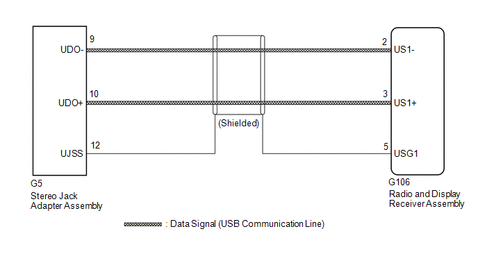
PROCEDURE
CHECK HARNESS AND CONNECTOR (RADIO AND DISPLAY RECEIVER ASSEMBLY - STEREO JACK ADAPTER ASSEMBLY)
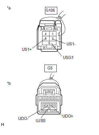
(a) Disconnect the G106 radio and display receiver assembly connector.
(b) Disconnect the G5 stereo jack adapter assembly connector.
(c) Measure the resistance according to the value(s) in the table below. Standard Resistance:
|
|
| OK |  |
PROCEED TO NEXT SUSPECTED AREA SHOWN IN PROBLEM SYMPTOMS TABLE |
| NG | |
REPAIR OR REPLACE HARNESS OR CONNECTOR |
Diagnostic Trouble Code Chart
DIAGNOSTIC TROUBLE CODE CHART
Audio and Visual SystemDTC No. | Detection Item | Link |
|---|---|---|
B1324 |
Lost Communication with Meter |
 |
B1551 |
HD Radio Tuner Malfunction |
|
B1579 |
Voice Recognition Microphone Disconnected |
|
B1585 |
USB Device Malfunction |
|
B158D |
Video Signal Stoppage |
|
B158F |
AV Signal Stoppage (Low Battery Voltage) |
|
B15A0 |
LAN Master Malfunction |
|
B15A3 |
Stereo Component Amplifier Malfunction |
|
B15B0 |
Display Screen Malfunction |
|
B15B3 |
Radio Tuner Malfunction |
|
B15B7 |
Bluetooth Module Malfunction |
|
B15BA |
XM Tuner Malfunction |
|
B15C0 |
GPS Antenna Connection Malfunction(short) |
|
B15C1 |
GPS Antenna Connection Malfunction(break) |
|
B15C3 |
Speaker Output Short |
|
B15D3 |
Stereo Component Amplifier Disconnected |
|
B15DB |
Telematics Transceiver Disconnected |
|
B15F5 |
Air Conditioner ECU Vehicle Information Reading/Writing Processor Malfunction |
|
B15F6 |
Main Body ECU Vehicle Information Reading/Writing Process Malfunction |
|
B15F7 |
Certification ECU Vehicle Information Reading/Writing Process Malfunction |
|
B15F9 |
UART Communication Malfunction(for A/C) |
|
B15FE |
XM Tuner Antenna Disconnected |
|
B15FF |
XM Tuner Antenna Short |
|
C1610 |
Camera ECU Malfunction |
|
U0073 |
Sending Malfunction (Navigation to APGS) |
|
U0100 |
Engine ECU Communication |
|
U0129 |
VSC(ECB)ECU Communication |
|
U0140 |
Lost Communication with Body Control Module |
|
U0155 |
Meter ECU Communication |
|
U0164 |
Air Conditioner ECU Communication |
|
U0198 |
Lost Communication with Telematic Control Module |
|
U0265 |
Lost Communication with Image Processing Sensor A |
|
U0293 |
HV ECU Communication |
|
Display does not Dim when Light Control Switch is Turned ON
NOTICE:
- Depending on the parts that are replaced during vehicle inspection or maintenance, performing initialization, registration or calibration may be needed. Refer to Precaution for Audio and Visual System.
Click here

- When replacing the radio and display receiver assembly, always replace it with a new one. If a radio and display receiver assembly which was installed to another vehicle is used, the following may occur:
- A communication malfunction DTC may be stored.
- The radio and display receiver assembly may not operate normally.
PROCEDURE
CHECK IMAGE QUALITY SETTING
(a) Turn the light control switch to the tail or head position.
(b) Check that the daytime screen setting on the display adjustment screen is set to on.
Result | Proceed to |
|---|---|
Daytime screen setting is set to on. |
A |
Daytime screen setting is set to off. |
B |
| A |  |
CHANGE DAYTIME SCREEN SETTING TO OFF |
|

CHECK VEHICLE SIGNAL (OPERATION CHECK)
(a) Enter the "Vehicle Signal Check Mode" screen. Refer to Check Vehicle Signal in Operation Check. Click here |
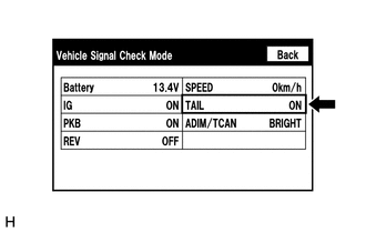 |
(b) Check that the display changes between ON and OFF according to the light control switch operation.
OK:
Light Control Switch | Display |
|---|---|
Tail or head |
ON |
Off or AUTO |
OFF |
HINT:
- The display is updated once per second. It is normal for the display to lag behind the actual switch operation.
- Make sure to move the vehicle to a bright area before performing an operation check with the light control switch in the AUTO position.
| OK | |
REPLACE RADIO AND DISPLAY RECEIVER ASSEMBLY |
| NG | |
PROCEED TO NEXT SUSPECTED AREA SHOWN IN PROBLEM SYMPTOMS TABLE |