Voice Recognition Microphone Disconnected (B1579). USB Device Malfunction (B1585). Black Screen
Voice Recognition Microphone Disconnected (B1579)
DESCRIPTION
The radio and display receiver assembly, roof console box sub-assembly and telephone microphone assembly are connected to each other using the microphone connection detection signal lines.
This DTC is stored when a microphone connection detection signal line is disconnected.
DTC No. | Detection Item | DTC Detection Condition | Trouble Area |
|---|---|---|---|
B1579 |
Voice Recognition Microphone Disconnected |
Microphone signal is lost |
|
- *: w/ Manual (SOS) Switch
WIRING DIAGRAM
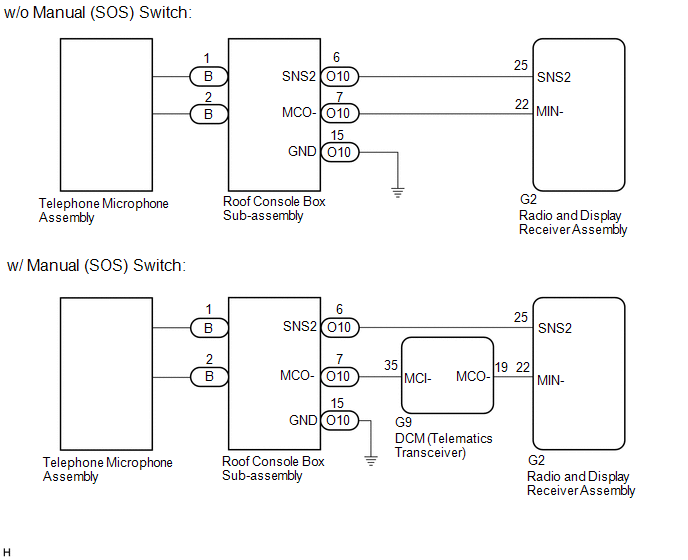
NOTICE:
- Depending on the parts that are replaced during vehicle inspection or maintenance, performing initialization, registration or calibration may be needed. Refer to Precaution for Navigation System.
Click here

- When replacing the radio and display receiver assembly, always replace it with a new one. If a radio and display receiver assembly which was installed to another vehicle is used, the following may occur:
- A communication malfunction DTC may be stored.
- The radio and display receiver assembly may not operate normally.
- Before replacing the DCM (telematics transceiver), refer to Registration.
Click here
PROCEDURE
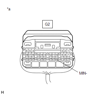
INSPECT RADIO AND DISPLAY RECEIVER ASSEMBLY
(a) Measure the resistance according to the value(s) in the table below. Standard Resistance:
|
|
| B |  |
GO TO STEP 3 |
| C | |
REPLACE RADIO AND DISPLAY RECEIVER ASSEMBLY |
|

CHECK HARNESS AND CONNECTOR (RADIO AND DISPLAY RECEIVER ASSEMBLY - ROOF CONSOLE BOX SUB-ASSEMBLY)
(a) Disconnect the G2 radio and display receiver assembly connector.
(b) Disconnect the O10 roof console box sub-assembly connector.
(c) Measure the resistance according to the value(s) in the table below.
Standard Resistance:
Tester Connection | Condition | Specified Condition |
|---|---|---|
G2-25 (SNS2) - O10-6 (SNS2) |
Always |
Below 1 Ω |
G2-22 (MIN-) - O10-7 (MCO-) |
Always |
Below 1 Ω |
G2-25 (SNS2) or O10-6 (SNS2) - Body ground |
Always |
10 kΩ or higher |
G2-22 (MIN-) or O10-7 (MCO-) - Body ground |
Always |
10 kΩ or higher |
| OK | |
GO TO STEP 7 |
| NG | |
REPAIR OR REPLACE HARNESS OR CONNECTOR |
CHECK HARNESS AND CONNECTOR (DCM (TELEMATICS TRANSCEIVER) - ROOF CONSOLE BOX SUB-ASSEMBLY)
(a) Disconnect the G9 DCM (telematics transceiver) connector.
(b) Disconnect the O10 roof console box sub-assembly connector.
(c) Measure the resistance according to the value(s) in the table below.
Standard Resistance:
Tester Connection | Condition | Specified Condition |
|---|---|---|
G9-35 (MCI-) - O10-7 (MCO-) |
Always |
Below 1 Ω |
G9-35 (MCI-) or O10-7 (MCO-) - Body ground |
Always |
10 kΩ or higher |
| NG | |
REPAIR OR REPLACE HARNESS OR CONNECTOR |
|
CHECK HARNESS AND CONNECTOR (RADIO AND DISPLAY RECEIVER ASSEMBLY - DCM (TELEMATICS TRANSCEIVER))
(a) Disconnect the G2 radio and display receiver assembly connector.
(b) Disconnect the G9 DCM (telematics transceiver) connector.
(c) Measure the resistance according to the value(s) in the table below.
Standard Resistance:
Tester Connection | Condition | Specified Condition |
|---|---|---|
G2-22 (MIN-) - G9-19 (MCO-) |
Always |
Below 1 Ω |
G2-22 (MIN-) or G9-19 (MCO-) - Body ground |
Always |
10 kΩ or higher |
| NG | |
REPAIR OR REPLACE HARNESS OR CONNECTOR |
|
CHECK HARNESS AND CONNECTOR (RADIO AND DISPLAY RECEIVER ASSEMBLY - ROOF CONSOLE BOX SUB-ASSEMBLY)
(a) Disconnect the G2 radio and display receiver assembly connector.
(b) Disconnect the O10 roof console box sub-assembly connector.
(c) Measure the resistance according to the value(s) in the table below.
Standard Resistance:
Tester Connection | Condition | Specified Condition |
|---|---|---|
G2-25 (SNS2) - O10-6 (SNS2) |
Always |
Below 1 Ω |
G2-25 (SNS2) or O10-6 (SNS2) - Body ground |
Always |
10 kΩ or higher |
| NG | |
REPAIR OR REPLACE HARNESS OR CONNECTOR |
|
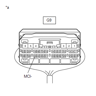
INSPECT DCM (TELEMATICS TRANSCEIVER)
(a) Connect the G9 DCM (telematics transceiver) connector.
(b) Connect the G2 radio and display receiver assembly connector.
(c) Measure the resistance according to the value(s) in the table below. Standard Resistance:
|
|
| NG | |
REPLACE DCM (TELEMATICS TRANSCEIVER) |
|
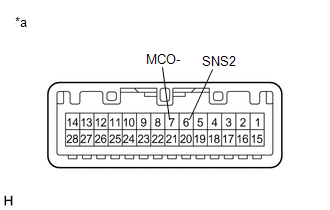
INSPECT ROOF CONSOLE BOX SUB-ASSEMBLY
(a) Remove the roof console box sub-assembly.
Click here
(b) Connect the B telephone microphone assembly connector.
(c) Measure the resistance according to the value(s) in the table below. Standard Resistance:
|
|
| OK | |
REPLACE RADIO AND DISPLAY RECEIVER ASSEMBLY |
|
INSPECT ROOF CONSOLE BOX SUB-ASSEMBLY
(a) Remove the roof console box sub-assembly.
Click here
(b) Disconnect the B telephone microphone assembly connector.
(c) Measure the resistance according to the value(s) in the table below. Standard Resistance:
|
|
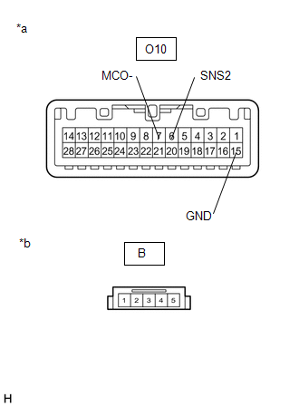
| OK | |
REPLACE TELEPHONE MICROPHONE ASSEMBLY |
| NG | |
REPLACE ROOF CONSOLE BOX SUB-ASSEMBLY |
USB Device Malfunction (B1585)
DESCRIPTION
This DTC is stored when a malfunction occurs in a connected device.
DTC No. | Detection Item | DTC Detection Condition | Trouble Area |
|---|---|---|---|
B1585 |
USB Device Malfunction |
When any of the following conditions is met:
|
|
NOTICE:
- Depending on the parts that are replaced during vehicle inspection or maintenance, performing initialization, registration or calibration may be needed. Refer to Precaution for Navigation System.
Click here

- When replacing the radio and display receiver assembly, always replace it with a new one. If a radio and display receiver assembly which was installed to another vehicle is used, the following may occur:
- A communication malfunction DTC may be stored.
- The radio and display receiver assembly may not operate normally.
PROCEDURE
REPLACE USB DEVICE OR "iPod"
(a) Disconnect the USB device or "iPod" from the stereo jack adapter assembly.
(b) Turn the engine switch off.
HINT:
When this DTC has been stored, it is necessary to turn the engine switch off to make it possible for the vehicle to recognize a new device when it is connected.
(c) Turn the engine switch on (ACC).
(d) Connect a known good USB device or "iPod" to the stereo jack adapter assembly.
HINT:
- If the malfunction occurred when a USB device was in use, use another USB device for the inspection. If the malfunction occurred when an "iPod" was in use, use another "iPod" for the inspection.
- Refer to System Description for compatible formats and versions.
Click here
|

CHECK DTC
(a) Clear the DTCs.
Body Electrical > Navigation System > Clear DTCs(b) Recheck for DTCs and check that no DTCs are output.
Body Electrical > Navigation System > Trouble CodesOK:
No DTCs are output.
| OK |  |
END (USB DEVICE FORMAT WAS INCOMPATIBLE, "iPod" VERSION WAS INCOMPATIBLE, OR USB DEVICE OR "iPod" WAS DEFECTIVE) |
| NG | |
REPLACE RADIO AND DISPLAY RECEIVER ASSEMBLY |
Black Screen
PROCEDURE
CHECK DISPLAY SETTING
(a) Check that the display is not in screen off mode.
OK:
The display setting is not in screen off mode.
| NG |  |
CHANGE SCREEN TO SCREEN ON MODE |
|

CHECK IMAGE QUALITY SETTING
(a) Check that the screen color quality can be set.
OK:
Setting is possible.
| OK | |
SET SCREEN COLOR QUALITY TO NORMAL |
| NG | |
PROCEED TO NEXT SUSPECTED AREA SHOWN IN PROBLEM SYMPTOMS TABLE |