Radio Receiver Power Source Circuit. Registered Device cannot be Deleted. Reverse Signal Circuit
Radio Receiver Power Source Circuit
DESCRIPTION
This is the power source circuit to operate the radio and display receiver assembly.
WIRING DIAGRAM
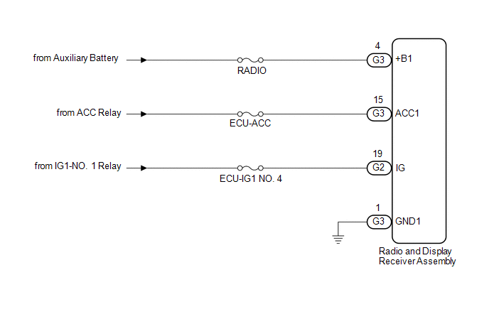
NOTICE:
Inspect the fuses for circuits related to this system before performing the following procedure.
PROCEDURE
CHECK HARNESS AND CONNECTOR (RADIO AND DISPLAY RECEIVER ASSEMBLY POWER SOURCE)
(a) Disconnect the G3 and G2 radio and display receiver assembly connectors.
(b) Measure the resistance according to the value(s) in the table below.
Standard Resistance:
Tester Connection | Condition | Specified Condition |
|---|---|---|
G3-1 (GND1) - Body ground |
Always |
Below 1 Ω |
(c) Measure the voltage according to the value(s) in the table below.
Standard Voltage:
Tester Connection | Condition | Specified Condition |
|---|---|---|
G3-4 (+B1) - G3-1 (GND1) |
Power switch off |
11 to 14 V |
G3-15 (ACC1) - G3-1 (GND1) |
Power switch on (ACC) |
11 to 14 V |
G2-19 (IG) - G3-1 (GND1) |
Power switch on (IG) |
11 to 14 V |
| OK |  |
PROCEED TO NEXT SUSPECTED AREA SHOWN IN PROBLEM SYMPTOMS TABLE |
| NG | |
REPAIR OR REPLACE HARNESS OR CONNECTOR |
Registered Device cannot be Deleted
PROCEDURE
DELETE OPERATION
(a) Check if a registered portable player can be deleted normally.
OK:
Registered portable player can be deleted normally.
| OK |  |
END |
| NG | |
PROCEED TO NEXT SUSPECTED AREA SHOWN IN PROBLEM SYMPTOMS TABLE |
Reverse Signal Circuit
DESCRIPTION
The radio and display receiver assembly receives a reverse signal from the BKUP LP relay.
WIRING DIAGRAM
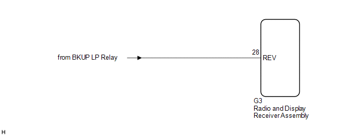
PROCEDURE
CHECK BACK-UP LIGHT
(a) Move the shift lever to R and check if the back-up lights come on.
OK:
The back-up lights come on.
| NG |  |
GO TO LIGHTING SYSTEM |
|

CHECK HARNESS AND CONNECTOR (REVERSE SIGNAL)
(a) Disconnect the G3 radio and display receiver assembly connector.
(b) Measure the voltage according to the value(s) in the table below.
Standard Voltage:
Tester Connection | Condition | Specified Condition |
|---|---|---|
G3-28 (REV) - Body ground |
Power switch on (IG) Shift lever in R |
11 to 14 V |
G3-28 (REV) - Body ground |
Power switch on (IG) Shift lever not in R |
Below 1 V |
| OK | |
PROCEED TO NEXT SUSPECTED AREA SHOWN IN PROBLEM SYMPTOMS TABLE |
| NG | |
REPAIR OR REPLACE HARNESS OR CONNECTOR |