Dcm(telematics Transceiver)
Components
COMPONENTS
ILLUSTRATION
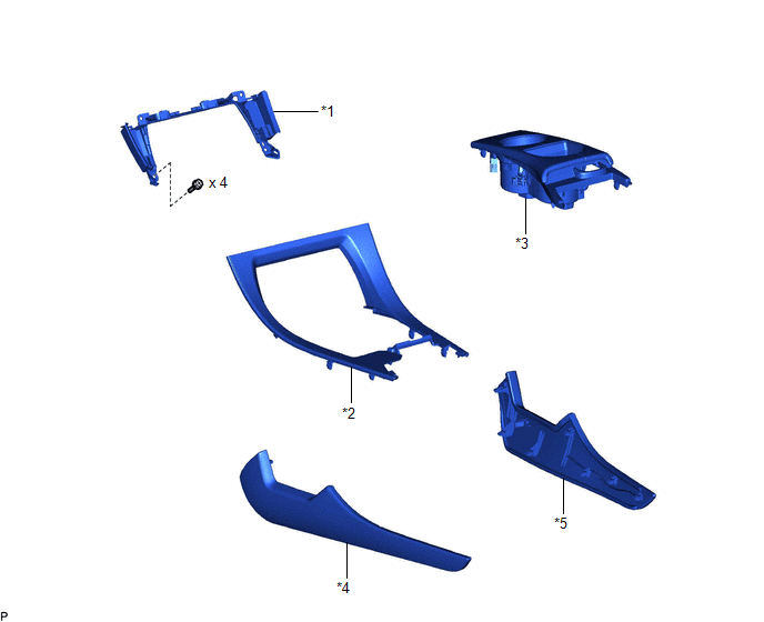
*1 |
CENTER INSTRUMENT CLUSTER FINISH PANEL SUB-ASSEMBLY |
*2 |
CONSOLE BOX POCKET SUB-ASSEMBLY |
*3 |
FRONT CONSOLE UPPER PANEL GARNISH |
*4 |
LOWER INSTRUMENT PANEL FINISH PANEL LH |
*5 |
LOWER INSTRUMENT PANEL FINISH PANEL RH |
- |
- |
ILLUSTRATION
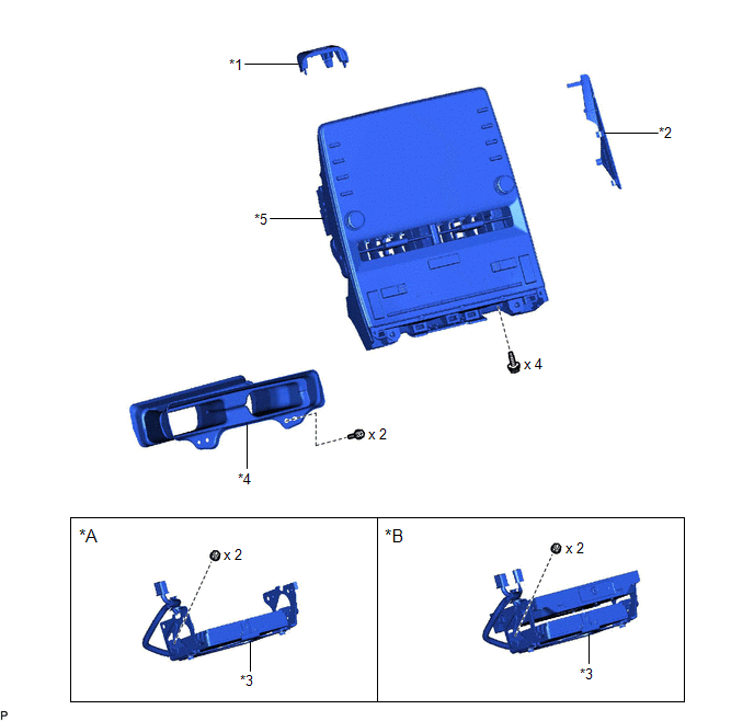
*A |
w/o Navigation System |
*B |
w/ Navigation System |
*1 |
CENTER NO. 1 INSTRUMENT CLUSTER FINISH PANEL |
*2 |
CENTER NO. 2 INSTRUMENT CLUSTER FINISH PANEL |
*3 |
DCM (TELEMATICS TRANSCEIVER) WITH BRACKET |
*4 |
NO. 2 HEATER TO REGISTER DUCT SUB-ASSEMBLY |
*5 |
RADIO AND DISPLAY RECEIVER ASSEMBLY WITH BRACKET |
- |
- |
ILLUSTRATION
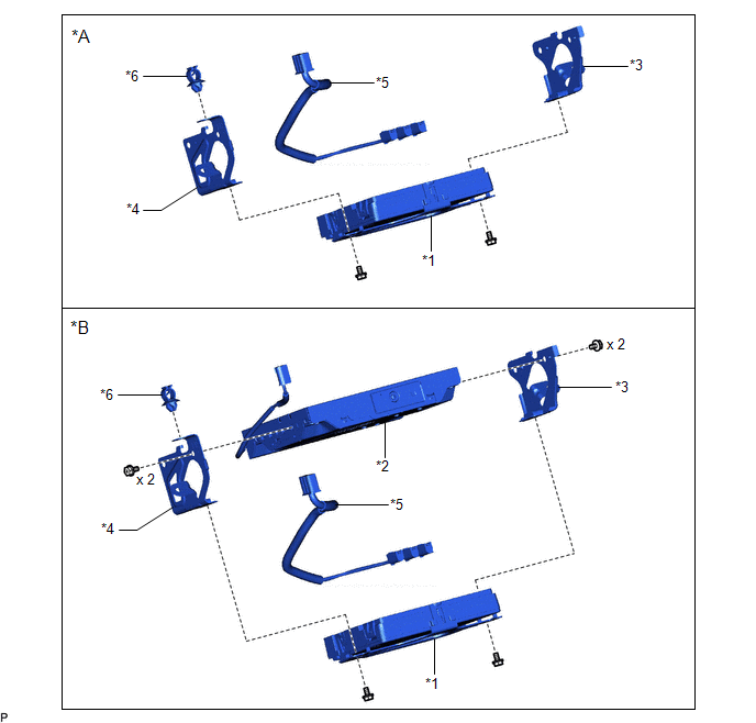
*A |
w/o Navigation System |
*B |
w/ Navigation System |
*1 |
DCM (TELEMATICS TRANSCEIVER) ASSEMBLY |
*2 |
NAVIGATION ECU WITH ANTENNA CORD |
*3 |
NO. 1 TELEPHONE BRACKET |
*4 |
NO. 2 TELEPHONE BRACKET |
*5 |
TELEPHONE AND GPS ANTENNA CORD |
*6 |
WIRING HARNESS CLAMP |
ILLUSTRATION
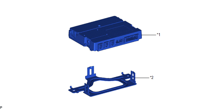
*1 |
DCM (TELEMATICS TRANSCEIVER) |
*2 |
NO. 3 TELEPHONE BRACKET |
Installation
INSTALLATION
PROCEDURE
1. INSTALL DCM (TELEMATICS TRANSCEIVER)
2. INSTALL NO. 3 TELEPHONE BRACKET
(a) Engage the 3 claws to install the No. 3 telephone bracket as shown in the illustration.
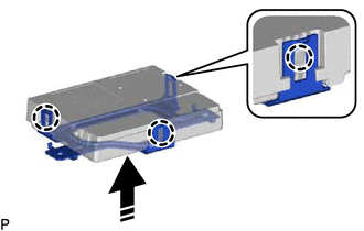
 |
Install in this Direction |
3. INSTALL DCM (TELEMATICS TRANSCEIVER) ASSEMBLY
4. INSTALL NAVIGATION ECU WITH ANTENNA CORD (w/ Navigation System)
5. INSTALL NO. 1 TELEPHONE BRACKET
(a) w/o Navigation System:
(1) Engage the 2 guides and install the No. 1 telephone bracket with the screw.
(b) w/ Navigation System:
(1) Engage the 3 guides and install the No. 1 telephone bracket with the 3 screws.
6. INSTALL NO. 2 TELEPHONE BRACKET
(a) w/o Navigation System:
(1) Engage the 2 guides and install the No. 2 telephone bracket with the screw.
(2) Engage the wiring harness clamp.
(b) w/ Navigation System:
(1) Engage the 3 guides and install the No. 2 telephone bracket with the 3 screws.
(2) Engage the wiring harness clamp.
(3) Engage the clamp.
7. INSTALL TELEPHONE AND GPS ANTENNA CORD
Click here 
8. INSTALL DCM (TELEMATICS TRANSCEIVER) WITH BRACKET
(a) w/o Navigation System:
(1) Connect each connector.
(2) Install the DCM (telematics transceiver) with bracket with the 2 nuts as shown in the illustration.
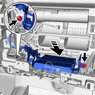
|
Install in this Direction |
(3) Connect the connector.
(b) w/ Navigation System:
(1) Connect each connector.
(2) Install the DCM (telematics transceiver) with bracket with the 2 nuts as shown in the illustration.
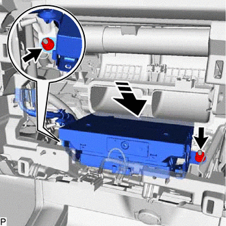
|
Install in this Direction |
(3) Connect the 2 connectors.
9. INSTALL NO. 2 HEATER TO REGISTER DUCT SUB-ASSEMBLY
Click here
10. INSTALL RADIO AND DISPLAY RECEIVER ASSEMBLY WITH BRACKET
Click here
11. INSTALL CENTER NO. 2 INSTRUMENT CLUSTER FINISH PANEL
Click here
12. INSTALL CENTER NO. 1 INSTRUMENT CLUSTER FINISH PANEL
Click here
13. INSTALL CENTER INSTRUMENT CLUSTER FINISH PANEL SUB-ASSEMBLY
Click here
14. INSTALL CONSOLE BOX POCKET SUB-ASSEMBLY
Click here
15. INSTALL FRONT CONSOLE UPPER PANEL GARNISH
Click here
16. INSTALL LOWER INSTRUMENT PANEL FINISH PANEL RH
Click here
17. INSTALL LOWER INSTRUMENT PANEL FINISH PANEL LH
Click here
18. PERFORM DCM ACTIVATION
HINT:
After replacing the DCM (telematics transceiver), make sure to perform DCM activation.
for Gasoline Model: Click here
for HV Model: Click here
19. PERFORM REGISTRATION
for Toyota Entune Remote Connect Compatible Type:
HINT:
After replacing the DCM (telematics transceiver), make sure to perform code registration (Smart key System (for Start Function)).
for Gasoline Model: Click here
for HV Model: Click here
Removal
REMOVAL
The necessary procedures (adjustment, calibration, initialization, or registration) that must be performed after parts are removed and installed, or replaced during DCM (telematics transceiver) removal/installation are shown below.
Necessary Procedure After Parts Removed/Installed/Replaced (for Gasoline Model)Replaced Part or Performed Procedure | Necessary Procedure | Effect/Inoperative Function When Necessary Procedures are not Performed | Link |
|---|---|---|---|
| *: for Toyota Entune Remote Connect Compatible Type | |||
Replacement of DCM (telematics transceiver) |
DCM activation |
Safety Connect System |
 |
Replacement of DCM (telematics transceiver)* |
Code registration (Smart key System (for Start Function)) |
Smart Key System (for Start Function) |
|
Replaced Part or Performed Procedure | Necessary Procedure | Effect/Inoperative Function When Necessary Procedures are not Performed | Link |
|---|---|---|---|
| *: for Toyota Entune Remote Connect Compatible Type | |||
Replacement of DCM (telematics transceiver) |
DCM activation |
Safety Connect System |
|
Replacement of DCM (telematics transceiver)* |
Code registration (Smart key System (for Start Function)) |
Smart Key System (for Start Function) |
|
PROCEDURE
1. REMOVE LOWER INSTRUMENT PANEL FINISH PANEL LH
Click here
2. REMOVE LOWER INSTRUMENT PANEL FINISH PANEL RH
Click here
3. REMOVE FRONT CONSOLE UPPER PANEL GARNISH
Click here
4. REMOVE CONSOLE BOX POCKET SUB-ASSEMBLY
Click here
5. REMOVE CENTER INSTRUMENT CLUSTER FINISH PANEL SUB-ASSEMBLY
Click here
6. REMOVE CENTER NO. 1 INSTRUMENT CLUSTER FINISH PANEL
Click here
7. REMOVE CENTER NO. 2 INSTRUMENT CLUSTER FINISH PANEL
Click here
8. REMOVE RADIO AND DISPLAY RECEIVER ASSEMBLY WITH BRACKET
Click here
9. REMOVE NO. 2 HEATER TO REGISTER DUCT SUB-ASSEMBLY
Click here
10. REMOVE DCM (TELEMATICS TRANSCEIVER) WITH BRACKET
(a) w/o Navigation System:
(1) Disconnect the connector. |
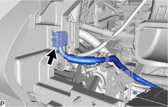 |
(2) Remove the 2 nuts and pull the DCM (telematics transceiver) with bracket as shown in the illustration.
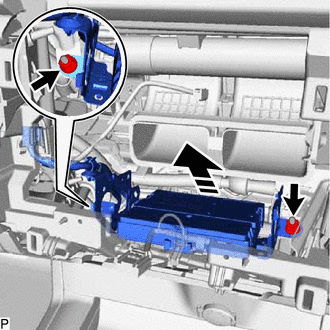
 |
Remove in this Direction |
(3) Disconnect each connector and remove the DCM (telematics transceiver) with bracket.
(b) w/ Navigation System:
(1) Disconnect the 2 connectors. |
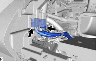 |
(2) Remove the 2 nuts and pull the DCM (telematics transceiver) with bracket as shown in the illustration.
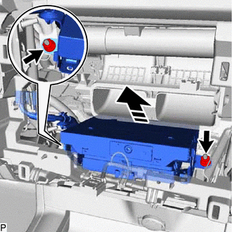
|
Remove in this Direction |
(3) Disconnect each connector and remove the DCM (telematics transceiver) with bracket.
11. REMOVE TELEPHONE AND GPS ANTENNA CORD
Click here
12. REMOVE NO. 2 TELEPHONE BRACKET
(a) w/o Navigation System:
(1) Disengage the wiring harness clamp. |
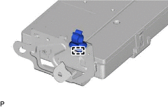 |
(2) Remove the screw and disengage the 2 guides to remove the No. 2 telephone bracket. |
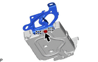 |
(b) w/ Navigation System:
(1) Disengage the clamp. |
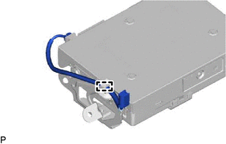 |
(2) Disengage the wiring harness clamp. |
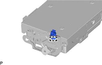 |
(3) Remove the 3 screws and disengage the 3 guides to remove the No. 2 telephone bracket. |
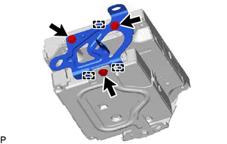 |
13. REMOVE NO. 1 TELEPHONE BRACKET
(a) w/o Navigation System:
(1) Remove the screw and disengage the 2 guides to remove the No. 1 telephone bracket. |
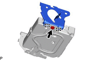 |
(b) w/ Navigation System:
(1) Remove the 3 screws and disengage the 3 guides to remove the No. 1 telephone bracket. |
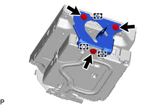 |
14. REMOVE NAVIGATION ECU WITH ANTENNA CORD (w/ Navigation System)
15. REMOVE DCM (TELEMATICS TRANSCEIVER) ASSEMBLY
16. REMOVE NO. 3 TELEPHONE BRACKET
(a) Disengage the 3 claws and remove the No. 3 telephone bracket as shown in the illustration.
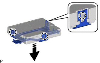
|
Remove in this Direction |
17. REMOVE DCM (TELEMATICS TRANSCEIVER)