Panoramic View Monitor Switch
Components
COMPONENTS
ILLUSTRATION
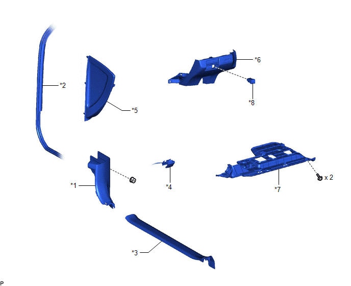
*1 |
COWL SIDE TRIM SUB-ASSEMBLY LH |
*2 |
FRONT DOOR OPENING TRIM WEATHERSTRIP LH |
*3 |
FRONT DOOR SCUFF PLATE LH |
*4 |
HOOD LOCK CONTROL LEVER SUB-ASSEMBLY |
*5 |
INSTRUMENT SIDE PANEL LH |
*6 |
NO. 1 INSTRUMENT PANEL SUB-ASSEMBLY |
*7 |
NO. 1 INSTRUMENT PANEL UNDER COVER SUB-ASSEMBLY |
*8 |
PANORAMIC VIEW MONITOR SWITCH |
Inspection
INSPECTION
PROCEDURE
1. INSPECT PANORAMIC VIEW MONITOR SWITCH
(a) Remove the panoramic view monitor switch
Click here 
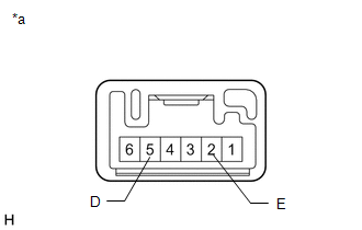
(b) Measure the resistance according to the value(s) in the table below. Standard Resistance:
If the result is not as specified, replace the panoramic view monitor switch. |
|
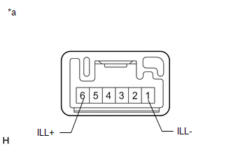
(c) Check that the switch illumination illuminates.
(1) Apply battery voltage to the panoramic view monitor switch and check that the switch illumination illuminates. OK:
If the result is not as specified, replace the integration control & panel assembly. |
|
(d) Install the panoramic view monitor switch.
Click here
Installation
INSTALLATION
PROCEDURE
1. INSTALL PANORAMIC VIEW MONITOR SWITCH
(a) Engage the 2 claws to install the panoramic view monitor switch as shown in the illustration.
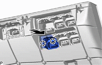
 |
Install in this Direction |
2. INSTALL NO. 1 INSTRUMENT PANEL SUB-ASSEMBLY
Click here 
3. CONNECT HOOD LOCK CONTROL LEVER SUB-ASSEMBLY
Click here
4. INSTALL NO. 1 INSTRUMENT PANEL UNDER COVER SUB-ASSEMBLY
Click here
5. INSTALL INSTRUMENT SIDE PANEL LH
Click here
6. INSTALL FRONT DOOR OPENING TRIM WEATHERSTRIP LH
Click here
7. INSTALL COWL SIDE TRIM SUB-ASSEMBLY LH
Click here
8. INSTALL FRONT DOOR SCUFF PLATE LH
Click here
Removal
REMOVAL
PROCEDURE
1. REMOVE FRONT DOOR SCUFF PLATE LH
Click here 
2. REMOVE COWL SIDE TRIM SUB-ASSEMBLY LH
Click here
3. DISCONNECT FRONT DOOR OPENING TRIM WEATHERSTRIP LH
Click here
4. REMOVE INSTRUMENT SIDE PANEL LH
Click here
5. REMOVE NO. 1 INSTRUMENT PANEL UNDER COVER SUB-ASSEMBLY
Click here
6. DISCONNECT HOOD LOCK CONTROL LEVER SUB-ASSEMBLY
Click here
7. REMOVE NO. 1 INSTRUMENT PANEL SUB-ASSEMBLY
Click here
8. REMOVE PANORAMIC VIEW MONITOR SWITCH
(a) Using a screwdriver with its tip wrapped with protective tape, disengage the 2 claws and remove the panoramic view monitor switch as shown in the illustration.
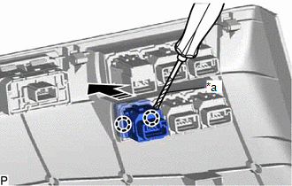
*a |
Protective Tape |
 |
Remove in this Direction |