Oil Pump
GENERAL INFORMATION

Oil Pump Components
1. Timing chain cover
2. Oil pump cover
3. Pump cover screw
4. Pump cover bolts
5. Oil strainer bracket mounting nut
6. Oil strainer pipe bolts
7. Oil strainer with coarse filter
8. O-ring
9. Drive rotor
10. Driven rotor
11. Relief valve plunger
12. Spring
13. Sealing washer
14. Relief valve plug
Disassembly The oil pump is integral with the timing chain cover. Remove the cover (refer to Subsection 3.2.1.6).
Condition Inspection
PROCEDURE
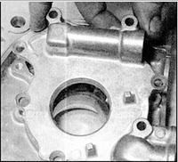
1. Remove the screws and bolt, and remove the pump cover from the rear side of the timing chain cover.
2. Unscrew the relief valve plug from the base of the timing chain cover and remove the sealing washer. Remove the spring and relief valve plunger, noting the correct orientation of the plunger.

3. Remove the drive and driven rotors from the timing chain cover.
4. Inspect the rotors, relief valve plunger and pump cover. Check for obvious signs of wear or damage.

5. Install the rotors in the cover. Use feeler gauges to check the clearance between the driven rotor and the pump body, and the clearance between the teeth of the driven and drive rotors.

6. Also check the clearance between the teeth of the driven and drive rotors.

7. Using a straightedge laid across the upper surface of the pump body and a feeler gauge, check the axial end play of the driven and drive rotors.
8. If the appropriate measuring instruments are available, measure the outer diameter of the driven rotor and the inner diameter of the pump body. Determine the clearance between the driven rotor and the pump body, which equals the inner diameter of the pump body minus the outer diameter of the driven rotor.
9. If signs of damage are present, or if any measured pump clearances exceed the specification, replace the timing chain cover.
10. If severe rotor wear is found, also check the condition of the relief valve. The relief valve is located inside the oil filter housing, which is screwed into the rear of the cylinder block. Remove the valve bolt from the top of the oil filter housing, and remove the sealing washer, spring and ball. Inspect all parts for signs of wear, and replace parts as necessary. When assembling, install the ball with the spring in the housing, fit a new sealing washer onto the valve bolt, screw in the bolt and tighten to the specified torque.
11. Lubricate the oil pump rotors with clean engine oil and install them in the housing. The driven rotor must be installed with its shoulder facing outward.
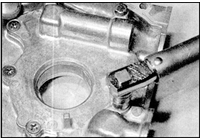
12. Install the cover, after first making sure the mating surface is clean. Install and tighten the cover bolt and screws to the specified torque.
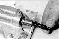
13. Install the relief valve plunger, keeping its original orientation, then install the spring.

14. Fit a new sealing washer onto the relief valve plug, then screw in the plug with the washer.
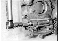
15. Tighten the bolt to the specified torque.
Assembly Assemble and install the timing chain cover (refer to Subsection 3.2.1.6).
Test yourself
A quick Nissan Sunny quiz: every answer comes with an explanation and a link to the manual page.