Removal and Inspection of Crankshaft
Removal
PROCEDURE
1. Remove the oil pan, timing chain (or chains) and flywheel.
2. Remove the connecting rods with pistons.
Warning: If no repair work will be performed on the pistons and connecting rods, it is not necessary to remove the cylinder head and piston-connecting rod assembly. The pistons should only be pushed toward the combustion chambers to move them a sufficient distance away from the crankshaft supports.
3. Check the crankshaft end play, then perform the following operations.
Engine 2 L
4. Remove the bolts and remove the rear oil seal retainer from the left side (flywheel side) of the cylinder block. If the guide pins are loose, remove them and store them together with the retainer.
5. Remove the main bearing cap bolts, loosening each bolt 1 turn at a time. Once the bolts are loosened, remove them from the cylinder block.

6. Remove the cast main bearing cap ladder from the main bearing caps, noting its orientation.

7. Main bearing caps must be numbered from 1 to 5, starting from the timing chain cover end (the numbering location is indicated by arrows). If the numbers are missing, mark each cap with white paint to indicate its sequence number and orientation, to prevent incorrect installation of the caps during assembly.
8. Remove the caps and take out the lower main bearing inserts. Tape each insert to its corresponding cap to prevent loss or incorrect installation of the inserts.
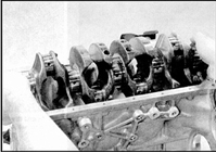
9. Carefully remove the crankshaft. Do not allow the upper main bearing inserts to move out of position.
10. Remove the upper main bearing inserts from the cylinder block. Tape each insert to its corresponding cap to prevent loss or incorrect installation of the inserts. Remove the thrust half-washers from the center main bearing journal (N3) and store them together with the center main bearing cap. Inspection of Condition
PROCEDURE
End Play Inspection1. Check the crankshaft end play before removing the crankshaft from the engine. The crankshaft must be able to move freely in the main bearings (refer to subsection 3.2.2.11).
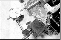
2. Check the crankshaft end play using a dial indicator with its tip touching the end of the crankshaft. Push the crankshaft fully in one direction and set the indicator dial to zero. Push the crankshaft fully in the opposite direction and read the indicator. Compare the result with the specification. If the end play exceeds the specification, replace the thrust half-washers.
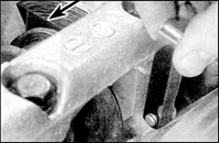
3. If a dial indicator is not available, the end play can be checked with a feeler gauge. Push the crankshaft fully toward the flywheel, then measure the clearance by inserting feeler gauges between the crankshaft web near the 4th connecting rod journal and the thrust half-washer next to the 3rd main bearing.
Condition Inspection
4. Wash the crankshaft with kerosene or solvent and dry it with compressed air (if available). Thoroughly clean the oil passages inside the crankshaft with a brush.
5. Inspect the connecting rod journals for uneven wear, cracks, scoring and pitting.
6. Uneven wear of a connecting rod journal causes a distinct metallic knocking noise while the engine is running (most clearly heard when the accelerator pedal is pressed during low-speed driving), and a noticeable drop in oil pressure.
7. Main bearing wear causes strong engine vibration and a dull rumbling noise that increases with engine speed, as well as a noticeable drop in oil pressure.
8. Check the crankshaft journals for roughness by running a finger over them without pressing hard. Any roughness (which appears together with clear signs of wear in the main and connecting rod bearings) indicates that the crankshaft journals must be reground (if possible) or the crankshaft must be replaced.
9. Check the runout of the center section of the crankshaft using a dial indicator, with the crankshaft set in V-blocks. If the runout exceeds the specification, replace the crankshaft.
10. If the crankshaft journals have been reground, remove burrs around the oil holes (these holes are normally slightly chamfered, so burrs occur only if grinding was performed carelessly). Remove burrs with a fine file or scraper, then thoroughly clean the holes.
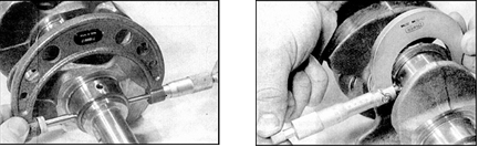
11. Measure the diameter of the main journals (photo left) and connecting rod journals (photo right) with a micrometer and compare the results with the specifications in the section (refer to subsection 3.2.1.1). Determine journal out-of-roundness by measuring the diameter at several points around the circumference of each journal. Check taper by measuring the diameter near opposite crank webs of each journal. Compare the results with the specifications.
12. Check the condition of the crankshaft journals that seal against the oil seals. If there is a deep groove worn at the sealing lip contact area, consult a specialist, as the crankshaft will require either repair or replacement.
13. The manufacturer supplies repair main and connecting rod bearings as spare parts. Only one repair size (0.25 mm) is available for main bearing inserts, and three repair sizes (0.08, 0.12 and 0.25 mm) are available for connecting rod bearings. To purchase repair main and connecting rod bearings, contact a Nissan dealer service center.
14. If repair bearings are available but crankshaft journal wear exceeds the specification to the point that further repair is not possible, it is advisable to purchase a reconditioned crankshaft and install repair bearings. Consult a service center or a specialist on further actions.
Test yourself
A quick Nissan Sunny quiz: every answer comes with an explanation and a link to the manual page.