Camshafts
GENERAL INFORMATION
The procedure described below recommends removing the chain. However, this is only necessary if the camshafts will be timed using the marks provided on the chain by the manufacturer. If the No. 1 piston is set to TDC of the compression stroke (see subsection 3.1.1.3), the marks on the driven camshaft sprockets may not align with the differently colored chain links (see subsection 3.2.1.7).Timing marks on the chain links and on both sprockets may be made by the owner and used to correctly orient the sprockets during assembly. This method is applicable under one condition: the sprockets must be installed without any change to their original orientation.
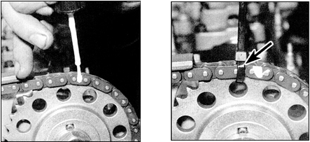
Relative Orientation Marks
To preserve the relative orientation of the sprocket and chain, it is advisable to apply orientation marks to each sprocket and to the chain, tie the sprockets to the chain, and ensure reliable mutual fixation. See figure (the arrow indicates tying with insulating tubing).
This method requires special care, but should significantly simplify the work for the vehicle owner, since it eliminates the need to remove the timing chain cover.
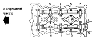
Main Bearing Cap Bolt Tightening Sequence
Removal
PROCEDURE
1. Remove the ignition distributor (see subsection 7.7.4).
2. Remove the chain and driven camshaft sprockets (see subsection 3.2.1.7). If the chain is to remain on the engine, apply orientation marks (see Relative Orientation Marks figure) and unscrew the sprocket bolts (see step 9 of subsection 3.2.1.7).
3. All camshaft bearing cap covers are identical, except for the front (right) cap of the exhaust camshaft. Therefore, before removing the caps, mark them for identification.
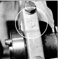
4. An arrow is cast into the top of the caps indicating the correct orientation of the cap during installation (all arrows must point toward the timing chain). The intake and exhaust camshafts have distinctive markings: "I" on the intake camshaft and "E" on the exhaust camshaft.
5. Using a marker or scriber, number all caps in sequence, starting from the front caps on the timing chain side. This ensures the caps are reinstalled in their original positions during assembly.
6. Loosen the camshaft bearing cap bolts, working in the reverse of the tightening sequence shown in the illustration. Camshaft Bearing Cap Bolt Tightening Sequence.
7. Loosen the bolts in several steps, one turn per step. This is necessary to evenly and gradually release the spring force from the valves acting on the caps. After the springs are fully released, the bolts can be removed completely. The cap bolts are divided into three length groups, so remember the position of each bolt as it is removed.
8. Remove the oil supply tube from the bearing caps, and remove the oil deflector plate from the 2nd cap. Remove the exhaust camshaft caps, then remove the exhaust camshaft.
9. Repeat steps 6–8 and remove the intake camshaft caps, then remove the intake camshaft (note that these caps do not have an oil deflector plate).
Condition Inspection
PROCEDURE
1. Inspect the surfaces contacting the camshaft journals in the caps and in the cylinder head. Check for scoring and deep wear marks. Check the camshaft lobes for metal flaking (bluish areas), deep wear, chips, and flat areas caused by wear.
2. Place the camshaft in V-blocks and use a dial indicator to check runout at the center journal. If runout exceeds the specification, replace the camshaft.
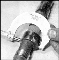
3. Measure each camshaft lobe with a micrometer and compare the results with the values specified in Subsection 3.2.1.
1. If signs of damage or excessive wear are found, replace the camshaft.
4. Next, check the clearance in the camshaft bearing journals. This can be done in two ways: either by direct measurement, or using Plastigage plastic gauge.
5. When measuring clearance by the direct method, install the camshaft bearing caps onto the cylinder head according to the marks made before disassembly, to maintain their original order and orientation. Install the oil supply tube and tighten the cap bolts to the specified torque, in the sequence shown in the illustration. Camshaft Bearing Cap Bolt Tightening Sequence. Measure the inside diameter of the cap bearing surfaces and compare with the value specified in Subsection 3.2.1.
1. If the inside diameter of any cap exceeds the limit, replace the cylinder head.
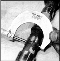
6. Clearance is determined as the difference between the inside diameter of the cap bearing surface and the diameter of the camshaft journal.
7. When measuring clearance with Plastigage, clean the camshafts and the bearing surfaces in the cylinder head and caps with a clean, lint-free cloth. Place the camshafts into the cylinder head.
8. Lay pieces of Plastigage wire along the camshaft journal surfaces, parallel to the shaft axis. Take measures to prevent the camshafts from rotating, then perform the actions described in steps 3–11 (see below), except the step involving applying sealant to the caps.
9. Loosen the cap bolts (see step 6 above) and carefully remove the caps and the oil supply tube, taking care not to rotate the camshafts.
10. Compare the widest width of the crushed wire from each journal with the scale on the gauge envelope to determine the clearance.
11. Compare the measurement result with the value specified in Subsection 3.2.1.
1. If the clearance exceeds the specification, measure the diameter of the camshaft journal with a micrometer. If the diameter is less than the minimum allowable, replace the camshaft and recheck the bearing journal clearances. If the clearances are still above specification, replace the cylinder head and the bearing caps.
Installation
PROCEDURE
1. Make sure each rocker arm is correctly engaged with its hydraulic lash adjuster and the guide disc installed on the valve actuated by that rocker arm.
2. Thoroughly lubricate the camshaft journal bearing surfaces in the cylinder head with clean engine oil.
3. Install the camshafts in their positions in the cylinder head. The exhaust camshaft can be easily identified by the slot on the left side for driving the ignition distributor.
4. Make sure the crankshaft is at TDC of the compression stroke (the keyway on the crankshaft nose must face straight up when viewed from the right side of the engine).
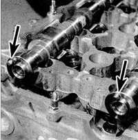
5. Install the camshafts in their positions in the cylinder head so that the lobes of cylinder 1 face away from the corresponding valves, aligning the pins on the ends (indicated by arrows). When the camshafts are correctly positioned, the locating pin on the front of the intake camshaft sprocket must point at 10 o'clock (viewed from the right side of the engine), and the pin on the exhaust camshaft must be in the upright vertical position.
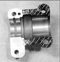
6. Make sure the contact surfaces of the bearing caps and the cylinder head seats are perfectly clean, free of foreign matter and oil. Apply a thin layer of sealant to the mating surface of the far-left exhaust camshaft cap, marked with diagonal hatching.
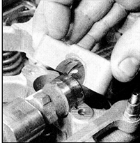
7. Install the bearing caps in their original order, aligning them with the marks made during disassembly.
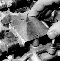
8. Install the oil baffle plate on the No. 2 exhaust camshaft cap and install the oil supply pipe.

9. Then install the oil supply pipes, securing them with the journal cap bolts. Install the journal cap bolts and tighten them by hand.
10. Tighten the intake camshaft cap mounting bolts in the specified sequence. Tighten the bolts evenly, gradually increasing the force, turning each bolt one turn at a time, until the caps contact the cylinder head (see illustration: Journal cap bolt tightening sequence). Then tighten the bolts to the specified torque. Perform tightening only in the specified order to ensure that the force from the valve springs on the journal caps increases evenly and gradually.
11. Tighten the exhaust camshaft cap bolts by repeating the procedure in the previous step.
12. Install the timing chain and camshaft sprockets (see Subsection 3.2.1.7).
13. If the chain was not removed, install the sprockets on the corresponding camshafts, install the chain, and align the marks on the chain and sprockets precisely with the marks made before disassembly. Install the sprocket bolts with washers, and tighten the bolts to the specified torque.
14. Install the distributor (see Subsection 7.7.4).
Test yourself
A quick Nissan Sunny quiz: every answer comes with an explanation and a link to the manual page.