Power unit with manual transmission
Removal WARNING: The engine may be removed from the vehicle together with the power unit (i.e. assembled with the transmission), after which the transmission is separated from the engine for major overhaul.
The power unit is lowered and removed from under the vehicle. To remove the engine this way without obstruction, raise the vehicle to a height of at least 75 cm (from the floor to the front bumper) and support it on stands.
PROCEDURE
1. Place the vehicle on a firm, level surface. Chock the rear wheels and apply the parking brake. Raise the front of the vehicle and support it on stands in accordance with all safety requirements.
2. Remove the front wheels.
3. Remove the screws and remove all engine undertray and splash shields.
4. Remove the hood.
5. Drain the coolant into a container (if the coolant is suitable for further use).
6. Drain the oil from the transmission. Install the drain plug and the fill/level plug, and tighten both plugs to the specified torque.
7. If the engine is to be disassembled, drain the oil and, if necessary, remove the oil filter. Clean and install the drain plug, and tighten it to the specified torque.
8. Remove the radiator assembly with hoses and fans.
9. Remove the alternator and disconnect the wiring from the starter motor.
10. Remove the power steering pump. Carbureted engines
11. On carbureted engines, remove or disconnect the following parts and assemblies: – air cleaner; – fuel supply hose and fuel return hose from the fuel pump (plug all openings to prevent fuel loss and contamination); – throttle cable; – wiring connectors from the carburetor; – brake booster vacuum hose, coolant hose, valve vacuum hoses and crankcase ventilation hoses mounted on the intake manifold; – intake manifold support bracket; – exhaust muffler inlet pipe.
12. On vehicles equipped with a catalytic converter, disconnect the connector from the exhaust gas sensor.
Single-point fuel injection engines
13. On single-point fuel injection engines (with pre-mixed fuel-air charge), remove the air cleaner.
14. Relieve the fuel system pressure, then disconnect the fuel supply hose and fuel return hose from the throttle body (plug all openings to prevent fuel loss and contamination).
15. Disconnect the throttle cable.
16. Disconnect the wiring connectors from the throttle body, intake manifold and other components.
17. Disconnect the brake booster vacuum hose, coolant hose, valve vacuum hoses and crankcase ventilation hoses mounted on the intake manifold.
18. Remove the intake manifold support bracket.
19. Remove the exhaust muffler inlet pipe.
Direct injection engines
20. On direct fuel injection engines, perform the following: remove the air cleaner intake duct.
21. Relieve the fuel system pressure, then disconnect the fuel supply hose and fuel return hose from the throttle body (plug all openings to prevent fuel loss and contamination).
22. Disconnect the throttle cable.

23. Disconnect the wiring connectors from the throttle body, intake manifold and other components. Move the wiring aside from the intake manifold and cylinder head so that it does not interfere with engine removal.
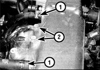
24. Disconnect the brake booster vacuum hose, coolant hose, valve vacuum hoses (1) and crankcase ventilation hoses from the intake manifold (2 – ground bolts).
25. Remove the intake manifold support bracket.
26. Loosen the clamps and disconnect the heater hoses and other cooling system hoses from the engine, first marking the original position of each hose.
27. On vehicles equipped with air conditioning, remove the compressor mounting bolts and move the compressor aside. Tie the compressor to the body so that its weight is not carried by the air conditioning lines and hoses. Do not disconnect the air conditioning hoses.
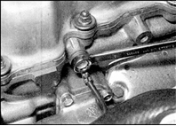
28. Referring to the description (see subsection 7.7.4), disconnect all wiring connectors from the ignition distributor, ignition coil and electronic control unit. Release the wiring harness from the clips on the cylinder head and move it aside. Remove the bolts and all ground wires from the cylinder head and intake manifold.
29. Remove the bolts and all ground wires from the cylinder head.
30. Remove the drive shafts assembled with the universal joints (see subsection 10.2).
31. Disconnect the clutch cable from the transmission (see subsection 8.3).
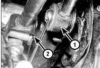
32. Disconnect the shift rod (1), gear selector linkage (2), speedometer cable and wiring connectors from the transmission.
33. Attach the hoist sling and secure it to the cylinder head brackets, then tension the hoist so that it supports the weight of the power unit.

34. Using paint or a marker, mark the position of the tie bolt (indicated by the arrow) on the front engine mount bracket so that the bolt can be installed in its original position during assembly.

35. Loosen and remove the nut of the clamp bolt (indicated by arrow), remove the bolt from the mount. Remove the nut and clamp bolt of the rear engine mount.

36. Remove the four bolts securing the center member, remove the member from under the engine.
37. Remove the nut and clamp bolt of the right engine mount, then remove the mount bolts and take the mount out of the engine compartment.
38. If the rubber cushions installed on both sides of the mount bracket on the body side are loose, remove the cushions.
39. Remove the clamp bolt of the left engine mount. Then remove the three bolts securing the mount to the transmission and move the mount aside. If the rubber cushions installed on both sides of the mount bracket are loose, remove the cushions.
40. Check once more that all parts, wires and hoses that could interfere with engine removal are disconnected or removed. Also make sure that no other vehicle parts will be bent or damaged during removal (for example the shift linkage and shift rod).
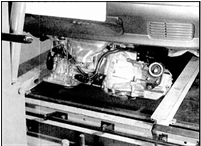
41. If a low trolley is available, position it under the engine to make it easier to remove the unit from under the vehicle. Lower the powertrain, taking care not to damage or catch nearby parts. It is advisable to perform this operation with an assistant, as the unit must be tilted slightly to avoid hitting body panels. Be extremely careful when lowering the engine.
42. Roll the powertrain out from under the vehicle.
Removing the Transmission from the Engine
PROCEDURE
1. Secure the removed powertrain with wooden blocks, placing it on a workbench or on a clean, level surface in the workshop.
2. Unbolt and remove the starter motor.
3. Make sure the powertrain is securely supported and remove the bolts securing the transmission case to the engine. Mark the location of the bolts (and of the corresponding brackets on some vehicles) so they can be reinstalled in their original positions.
4. Carefully separate the transmission from the engine, making sure the weight of the transmission is not supported by the input shaft as it comes out of the clutch driven disc.
5. If the transmission locating dowels are loose, remove them and store them so they can be reinstalled in their original positions.
Installation
PROCEDURE
1. If the transmission was removed from the engine, perform the operations described in steps 2–6 below. If the transmission was not removed, follow the installation procedure starting from step 7.
2. Apply a thin layer of high-melting-point grease to the splines of the transmission input shaft. Excess grease is not permitted, otherwise the friction disc may become contaminated with grease.
3. Install the dowels on the engine or transmission (if removed), and make sure the release bearing is securely seated on the clutch release fork.
4. Carefully install the transmission on the engine, guiding it over the locating dowels. During installation the weight of the transmission must not be carried by the input shaft while the shaft enters the splines of the clutch driven disc.
5. Install the transmission case bolts, making sure all brackets are installed correctly, and tighten the bolts to the specified torque.
6. Install the starter motor and tighten the bolts.
7. Position the powertrain under the vehicle and attach the hoist to the engine brackets.
8. With an assistant, raise the powertrain into the engine compartment, taking care not to hit nearby components.
9. Install the rubber mounts on the left engine mount bracket, making sure the mount studs enter the bracket holes. Install the mount in position, install the mount-to-transaxle bolts and tighten them to the specified torque. Insert the tension bolt and tighten the nut by hand.
10. Install the rubber mounts on the right suspension bracket on the body side, making sure the mount studs enter the holes in the bracket. Install the mount and tighten the bolts to the specified torque. Insert the tension bolt and tighten the nut by hand.
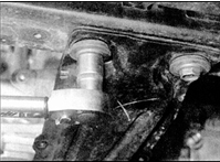
11. Make sure all rubber mounts are installed in their correct positions. Install the stopper ring on the rear mount. Install the center member, install the bolts with washers and tighten them by hand. Tighten the center member bolts to the specified torque.
12. Insert the rear mount through bolt and tighten the nut by hand.
13. Insert the front mount tension bolt. Position the powertrain so that the front mount tension bolt aligns exactly with the mark made before disassembly, then tighten the bolt to the specified torque.
14. Rock the powertrain to seat it in position, then tighten the tension bolts of the front, right and left mounts to the specified torque.
15. Install the powertrain in the reverse order of removal. During installation, make sure the wiring harness is routed along its original paths and secured with clips and brackets, and that all connectors are connected.
15. Replace the driveshaft seals and install the driveshafts on the transaxle.
16. Connect all cooling system hoses and secure them with clamps.
17. Adjust the throttle cable.
18. Connect and adjust the clutch cable (see subsection 8.3).
19. Install and adjust the drive belts.
20. Replace the engine and transmission oil. For recommended oil grades and fill capacities, see subsection 1.12.7.
21. Fill the cooling system with coolant.
22. After completing the work, start the engine and check for leaks.
Test yourself
A quick Nissan Sunny quiz: every answer comes with an explanation and a link to the manual page.