Valve Rocker Arms and Hydraulic Lash Adjusters
GENERAL INFORMATION
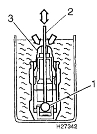
Air Bleeding the Hydraulic Lash Adjuster
1. Ball valve
2. Plunger rod
3. Plunger
Removal
PROCEDURE
1. Remove the camshafts (see Subsection 3.2.1.9).
2. Prepare 16 clean plastic bags and number them from 1 to
16. A box with 16 compartments may also be used.
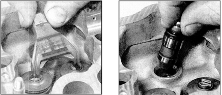
3. Remove the first valve rocker arm, extract the hydraulic lash adjuster from the cylinder head bore, and place it in the bag together with the rocker arm, keeping these parts in their operating position. Caution: The hydraulic lash adjuster must always be stored in its operating position. If it is stored horizontally or upside down, air will enter the adjuster and must be bled before installation, following the instructions in steps 9 and 10 (see below).
4. Remove the spacer shims and guide discs from the valve tips and place these parts in the bag together with the hydraulic lash adjuster.
5. Repeat step 3 and remove the rocker arms, hydraulic lash adjusters, spacer shims and guide discs for the remaining valves. Do not mix up the rocker arms and lash adjusters, otherwise these parts will be subject to accelerated wear.
Condition Inspection
PROCEDURE
1. Check the contact surface of the rocker arm with the camshaft cam lobe, and check this surface for signs of wear and damage. If the rocker arms are worn, the camshaft cams will also show increased wear (see Subsection 3.2.1.9). Replace the rocker arms if necessary.
2. Check the hydraulic lash adjusters and the mating bores in the cylinder head for signs of excessive wear. If the required measuring tools are available, the degree of wear can be determined by direct measurement. To do this, measure the inside diameter of the lash adjuster bore in the cylinder head and the outside diameter of the lash adjuster. The lash adjuster clearance equals the difference between these diameters. Compare the clearance obtained with the specification given in the Specifications section (see Subsection 3.2.1.1). Replace worn parts if necessary.
3. Check the guide discs of the rocker arms for signs of wear and replace them if necessary.
Installation
PROCEDURE
1. Before assembly, check the thickness of each spacer shim to determine whether it can be reused. This operation is especially necessary if new valves and valve seats will be installed, or if the valves have been refaced. The procedure for checking shim thickness is described in steps 2–
5. If the cylinder head has not been repaired and measuring the shim thickness is not necessary, continue assembly following step 8 and the subsequent steps.
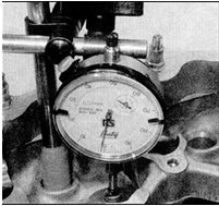
2. Install the rocker arm guide disc on the tip of the valve from which it was removed (this is very important, see step 13). Mount a dial indicator on the cylinder head and bring the movable probe of the indicator plunger into contact with the thrust surface of the guide disc that contacts the valve rocker arm. Set the indicator dial to zero.

3. Then carefully lift the indicator probe and rotate the indicator strictly parallel to its original position. Bring the indicator probe into contact with the tip of the other valve that will be actuated by the rocker arm, i.e., the second valve of the same cylinder.
Caution: When rotating the indicator, it must move strictly parallel to its original position; otherwise the readings will be incorrect.
4. Read the indicator value, which equals the distance between the valve stem tip and the thrust surface of the guide disc actuated by the rocker arm, and record this reading. To verify that the indicator head moved strictly parallel during measurement, rotate the head back to its original position, where the indicator probe contacts the thrust surface of the guide disc. The indicator reading on returning to the original position must be zero. Repeat the measurements described above for each pair of intake and exhaust valves in all cylinders. Record the results.
5. Based on the measurements, determine the suitable spacer shim thickness for each valve pair. The shim thickness must be exactly equal to the measured value; however, the manufacturer allows a tolerance of ±0.025 mm. Caution: Service shims are supplied with thicknesses from 2.800 to 3.200 mm in increments of 0.025 mm.
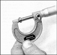
6. The thickness value is marked on the lower surface of the shim (for example, 2875 means a thickness of 2.875 mm). Nevertheless, it is advisable to measure the actual thickness of the shim being replaced with a micrometer, since its thickness may be reduced due to wear.
7. Install the shim spacers on the corresponding valve, making sure the marked surface faces down.
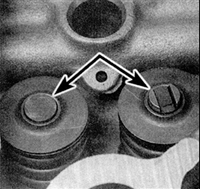
8. If the shim thickness was not measured, install the guide discs and adjusting shim spacers (indicated by arrows) on the corresponding valves, making sure the marked surface of the shims faces down.
9. Before installing the hydraulic lash adjusters, make sure there is no air inside them. To do this, press the adjuster plunger (the adjuster must be in a vertical position with the plunger facing up). The plunger should not move. If the plunger moves more than 1.0 mm, air is present inside the hydraulic lash adjuster. If air has entered the adjuster, or if a new adjuster is being installed, the air must be removed as follows. Warning: With the engine running, air is not released from the hydraulic lash adjusters automatically. If the adjusters are installed without removing the air inside, their normal operation will be disrupted and increased noise will be heard.
10. Prepare a small container slightly larger than the hydraulic lash adjuster, and a rod (for example, a piece of welding electrode) that fits into the hole in the adjuster plunger. Fill the container with clean engine oil of the same grade as that in the engine, and immerse the hydraulic lash adjuster in the oil, keeping it in the vertical operating position (plunger facing up). Insert the rod into the hole in the plunger and lightly press down on the ball valve of the adjuster (see figure Removing Air from the Hydraulic Lash Adjuster). Holding the rod in this position, slowly move the plunger up and down. Air will begin to escape from the space under the ball valve. After bubbles stop coming from the top of the hydraulic lash adjuster, release the plunger and remove the rod; the ball valve will then close. Warning: When releasing the plunger, keep the ball valve in the open position.
11. Remove the hydraulic lash adjuster from the container and check the plunger travel (see step 9).
12. After removing air from the hydraulic lash adjusters, install them in the cylinder head in their original positions.
13. Install the valve rocker arms in their original positions, making sure the rocker arms correctly engage the hydraulic lash adjusters and guide discs. Warning: The ends of the rocker arms that engage with the shim spacer and the guide bushing differ in width. The end on the shim spacer side is slightly wider than the end on the guide bushing side. If the rocker arm does not match the valve, its end will not fit into the slot on the end of the guide bushing.
14. Install the camshafts (see subsection 3.2.1.9).
Test yourself
A quick Nissan Sunny quiz: every answer comes with an explanation and a link to the manual page.