Speaker Output Short Circuit (B15C3)
DESCRIPTION
This DTC is stored when a malfunction occurs in the speakers.
DTC No. | Detection Item | DTC Detection Condition | Suspected Area |
|---|---|---|---|
B15C3 |
Speaker Output Short Circuit |
A short circuit is detected in the speaker output circuit. |
|
WIRING DIAGRAM
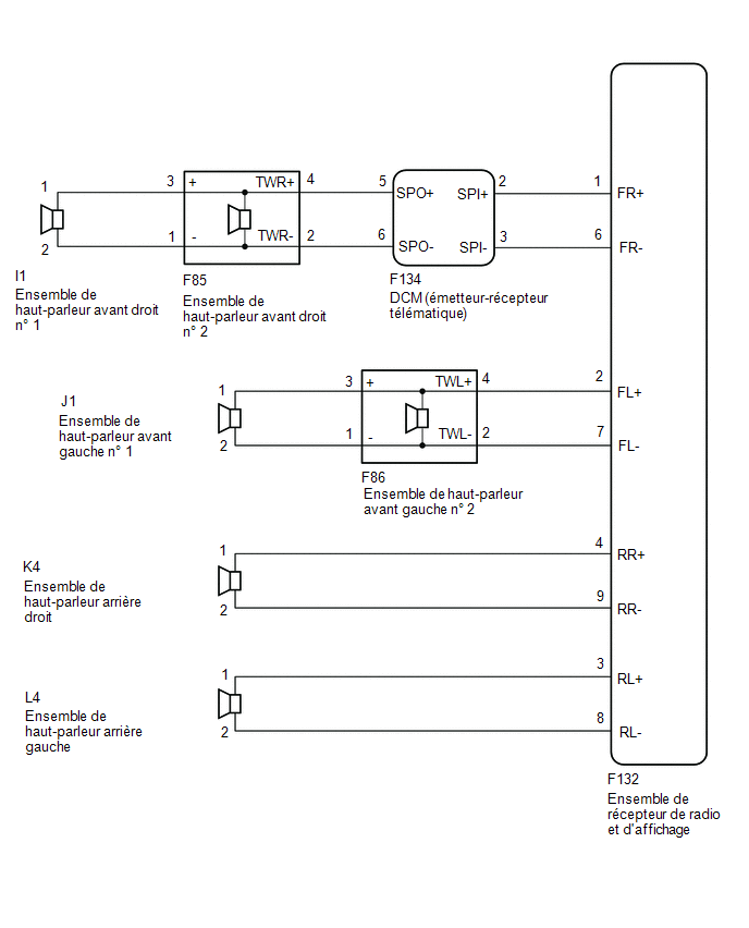
PRECAUTION / NOTICE / HINT
NOTICE:
- Depending on the parts replaced during vehicle inspection or maintenance, initialization, registration or calibration may be required. Refer to the precautions for the navigation system.
Click here

- When replacing the radio and display receiver assembly, always replace it with a new one. If a radio and display receiver assembly that was installed in another vehicle is reused, the following may occur:
- A communication malfunction DTC may be stored.
- The radio and display receiver assembly may not operate normally.
PROCEDURE
CHECK HARNESS AND CONNECTOR (RADIO RECEIVER AND DISPLAY ASSEMBLY, DCM (TELEMATICS TRANSCEIVER) OR SPEAKERS - BODY GROUND)
(a) Disconnect the F132 radio and display receiver assembly connector.
(b) Disconnect the No. 2 front speaker assembly connector F86.
(c) Disconnect the DCM (telematics transceiver) connector F134.
(d) Disconnect the K4 and L4 rear speaker assembly connectors.
(e) Measure the resistance according to the value(s) in the table below.
Standard resistance:
Tester Connection | Condition | Specified Condition |
|---|---|---|
F132-1 (FR+) or F134-2 (SPI+) - Body ground |
Always |
10 kΩ minimum |
F132-6 (FR-) or F134-3 (SPI-) - Body ground |
Always |
10 kΩ minimum |
F132-2 (FL+) or F86-4 (TWL+) - Body ground |
Always |
10 kΩ minimum |
F132-7 (FL-) or F86-2 (TWL-) - Body ground |
Always |
10 kΩ minimum |
F132-4 (RR+) or K4-1 - Body ground |
Always |
10 kΩ minimum |
F132-9 (RR-) or K4-2 - Body ground |
Always |
10 kΩ minimum |
F132-3 (RL+) or L4-1 - Body ground |
Always |
10 kΩ minimum |
F132-8 (RL-) or L4-2 - Body ground |
Always |
10 kΩ minimum |
| NG |  |
REPAIR OR REPLACE HARNESS OR CONNECTOR |
|

CHECK HARNESS AND CONNECTOR (FRONT RH NO. 2 SPEAKER ASSEMBLY OR DCM (TELEMATICS TRANSCEIVER) - BODY GROUND)
(a) Disconnect the F85 front RH No. 2 speaker assembly connector.
(b) Disconnect the F134 DCM (telematics transceiver) connector.
(c) Measure the resistance according to the value(s) in the table below.
Standard resistance:
Tester Connection | Condition | Specified Condition |
|---|---|---|
F85-4 (TWR+) or F134-5 (SPO+) - Body ground |
Always |
10 kΩ minimum |
F85-2 (TWR-) or F134-6 (SPO-) - Body ground |
Always |
10 kΩ minimum |
| NG | |
REPAIR OR REPLACE HARNESS OR CONNECTOR |
|
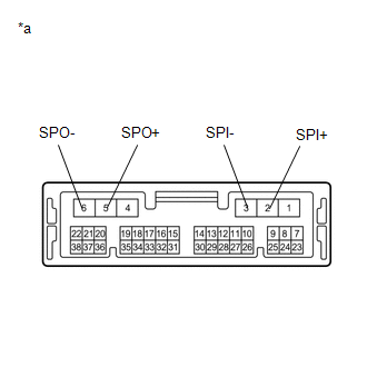
CHECK DCM (TELEMATICS TRANSCEIVER)
(a) Disconnect the DCM (telematics transceiver).
Click here
(b) Measure the resistance according to the value(s) in the table below. Standard resistance:
|
|
| NG | |
REPLACE DCM (DATA COMMUNICATION MODULE) |
|
CHECK HARNESS AND CONNECTOR (NO. 1 FRONT SPEAKER ASSEMBLY OR NO. 2 FRONT SPEAKER ASSEMBLY - BODY GROUND)
(a) Disconnect connectors I1 and J1 from the No. 1 front speaker assembly.
(b) Disconnect connectors F85 and F86 from the No. 2 front speaker assembly.
(c) Measure the resistance according to the value(s) in the table below.
Standard resistance:
Tester Connection | Condition | Specified Condition |
|---|---|---|
F85-3 (+) or I1-1 - Body ground |
Always |
10 kΩ minimum |
F85-1 (-) or I1-2 - Body ground |
Always |
10 kΩ minimum |
F86-3 (+) or J1-1 - Body ground |
Always |
10 kΩ minimum |
F86-1 (-) or J1-2 - Body ground |
Always |
10 kΩ minimum |
| NG | |
REPAIR OR REPLACE HARNESS OR CONNECTOR |
|
INSPECT NO. 1 FRONT SPEAKER ASSEMBLY
(a) Remove the No. 1 front speaker assembly.
Click here
(b) Inspect the No. 1 front speaker assembly.
Click here
| NG | |
REPLACE NO. 1 FRONT SPEAKER ASSEMBLY |
|
INSPECT NO. 2 FRONT SPEAKER ASSEMBLY
(a) Remove the No. 2 front speaker assembly.
Click here
(b) Inspect the No. 2 front speaker assembly.
Click here
(c) Clear the DTCs.
Click here
(d) Check the DTCs again and make sure no DTCs are output.
Body Electrical > Navigation System > Trouble CodesOK:
No DTC is output.
| OK | |
END |
|
INSPECT REAR SPEAKER ASSEMBLY
(a) Remove the rear speaker assembly.
Click here
(b) Inspect the rear speaker assembly.
Click here
| OK | |
REPLACE RADIO AND DISPLAY RECEIVER ASSEMBLY |
| NG | |
REPLACE REAR SPEAKER ASSEMBLY |