ECU Terminals
ECU TERMINALS
HINT:
Check from the rear of the connector while it is connected to the component parts.
RADIO AND DISPLAY RECEIVER ASSEMBLY
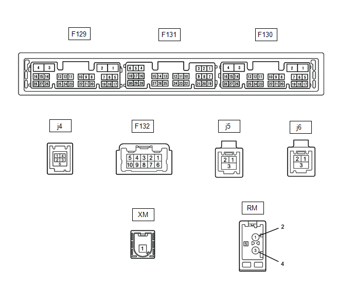
Terminal No. (Symbol) | Wire Color | Terminal Description | Condition | Specified Condition |
|---|---|---|---|---|
F132-1 (FR+) - F129-1 (GND1) |
LA-LG - LA |
Audio signal (front right) |
Audio system operates |
A waveform synchronized with the sound signals is emitted |
F132-2 (FL+) - F129-1 (GND1) |
W - LA |
Audio signal (front left) |
Audio system operates |
A waveform synchronized with the sound signals is emitted |
F132-3 (RL+) - F129-1 (GND1) |
B - LA |
Audio signal (rear left) |
Audio system operates |
A waveform synchronized with the sound signals is emitted |
F132-6 (FR-) - F129-1 (GND1) |
LA-L - LA |
Audio signal (front right) |
Audio system operates |
A waveform synchronized with the sound signals is emitted |
F132-7 (FL-) - F129-1 (GND1) |
B - LA |
Audio signal (front left) |
Audio system operates |
A waveform synchronized with the sound signals is emitted |
F132-8 (RL-) - F129-1 (GND1) |
Y - LA |
Audio signal (rear left) |
Audio system operates |
A waveform synchronized with the sound signals is emitted |
F129-1 (GND1) - Body ground |
LA - Body ground |
Ground |
Always |
Below 1 V |
F129-4 (+B1) - F129-1 (GND1) |
LA-SB - LA |
Power supply (+B) |
Engine switch in OFF position |
11 à 14 V |
F129-10 (AGND) - Body ground |
Shield - Body ground |
Shield ground |
Always |
Below 1 V |
F129-11 (VAL+) - F129-13 (VA-) |
B - R |
Audio signal (left) |
Auxiliary device operates (when a stereo plug is used) |
A waveform synchronized with the sound signals is emitted |
F129-12 (VAR+) - F129-13 (VA-) |
W - R |
Audio signal (right) |
Auxiliary device operates (when a stereo plug is used) |
A waveform synchronized with the sound signals is emitted |
F129-13 (VA-) - F129-1 (GND1) |
R - LA |
Ground |
Always |
Below 1 V |
F129-14 (ADPG) - F129-1 (GND1) |
R - LA |
Auxiliary device connection detection signal |
Auxiliary device is connected |
Below 1 V |
Auxiliary device is not connected |
2,1 à 3 V |
|||
F129-15 (ACC1) - F129-1 (GND1) |
GR - LA |
Power supply (ACC) |
Engine switch in OFF position |
Below 1 V |
Engine switch in ON (ACC) position |
11 à 14 V |
|||
F129-21 (SW1) - F129-24 (SWG) |
GR - W-B |
Steering wheel switch signal |
No switch pressed |
2,97 à 3,56 V |
SEEK+ switch pressed |
0,27 à 0,35 V |
|||
SEEK- switch pressed |
0,86 à 1,03 V |
|||
VOL+ switch pressed |
1,51 à 1,79 V |
|||
VOL- switch pressed |
2,22 à 2,66 V |
|||
F129-22 (SW2) - F129-24 (SWG) |
G - W-B |
Steering wheel switch signal |
No switch pressed |
2,97 à 3,56 V |
MODE switch pressed |
0,27 à 0,35 V |
|||
Off-hook switch pressed |
1,51 à 1,79 V |
|||
On-hook switch pressed |
0,86 à 1,03 V |
|||
VOICE switch pressed |
2,22 à 2,66 V |
|||
F129-24 (SWG) - F129-1 (GND1) |
W-B - LA |
Steering wheel switch ground |
Always |
Below 1 V |
F129-27 (SPD) - F129-1 (GND1) |
V - LA |
Vehicle speed signal |
See the "Vehicle Signal Check" section in Operation Check Click here |
- |
F129-28 (REV) - F129-1 (GND1) |
R - LA*1 L - LA*2 |
Reverse signal |
See the "Vehicle Signal Check" section in Operation Check  |
- |
F131-5 (CNH1) |
R |
Local bus communication signal |
- |
- |
F131-6 (CNL1) |
L |
Local bus communication signal |
- |
- |
F131-15 (ILL+) - F129-1 (GND1) |
G - LA |
Illumination signal |
Illumination control switch in OFF position |
Below 1 V |
Light control switch in TAIL or HEAD position |
11 à 14 V |
|||
F131-16 (ILL-) - F129-1 (GND1) |
B - LA |
Illumination signal |
Illumination control switch in OFF position |
Below 1 V |
Light control switch in TAIL or HEAD position |
Pulse generation |
|||
F131-19 (IG) - F129-1 (GND1) |
B - LA |
Power supply (IG) |
Engine switch in OFF position |
Below 1 V |
Engine switch in ON (IG) position |
11 à 14 V |
|||
F131-20 (PKB) - F129-1 (GND1) |
P - LA |
Parking brake signal |
See the "Vehicle Signal Check" section in Operation Check Click here |
- |
F131-21 (MIN+) - F129-1 (GND1) |
B - LA*1 G - LA*2 |
Microphone voice signal |
See the "Check Microphone" section in Operation Check Click here |
- |
F131-22 (MIN-) - F129-1 (GND1) |
W - LA*1 R - LA*2 |
Microphone voice signal |
See the "Check Microphone" section in Operation Check Click here |
- |
F131-23 (MACC) - F129-1 (GND1) |
B - LA |
Microphone power supply |
Engine switch in OFF position |
Below 1 V |
Engine switch in ON (ACC) position |
4 à 6 V |
|||
F131-24 (SGND) - Body ground |
Shield - Body ground |
Shield ground |
Always |
Below 1 V |
F131-25 (SNS2) - F129-1 (GND1) |
V - LA*1 G - LA*2 |
Microphone connection detection signal |
Always |
Below 1 V |
j4-1 (USVI) |
- |
Power source |
- |
- |
j4-2 (US1-) |
- |
Data signal |
- |
- |
j4-3 (US1+) |
- |
Data signal |
- |
- |
j4-4 (UGD1) |
- |
Ground |
- |
- |
j5-1 (USB+) |
- |
Data signal |
- |
- |
j5-2 (USB-) |
- |
Data signal |
- |
- |
j5-3 (USBG) |
- |
Shield ground |
- |
- |
j6-1 (GV-) |
- |
Video signal (digital) |
- |
- |
j6-2 (GV+) |
- |
Video signal (digital) |
- |
- |
j6-3 (GND) - Body ground |
- |
Shield ground |
Always |
Below 1 Ω |
F130-7 (SUP) - F129-1 (GND1) |
W - LA*1 R - LA*2 |
Start signal |
20 seconds elapse after the engine switch is set to ON (ACC) |
11 à 14 V |
F130-10 (USBV) |
Y |
DCM (Data Communication Module) power supply |
Engine switch in OFF position |
Below 1 V |
Engine switch in ON (ACC) position |
4,75 à 5,25 V |
|||
F130-11 (USBG) |
P |
Ground |
- |
- |
F130-12 (SGND) - Body Ground |
Shield - Body ground |
Shield ground |
Always |
Below 1 Ω |
F130-19 (RST)*3 |
L |
- |
- |
- |
F130-22 (SI+) - F129-1 (GND1) |
B - LA*1 W - LA*2 |
Voice signal |
Voice guidance output |
The output waveform is synchronized with the output sound |
F130-23 (SI-) - F129-1 (GND1) |
W - LA*1 B - LA*2 |
Voice signal |
Voice guidance output |
The output waveform is synchronized with the output sound |
F130-24 (SGND) - F129-1 (GND1) |
Shield - LA |
Shield ground |
Always |
Below 1 Ω |
F130-25 (MCO+) - F130-26 (MCO-) |
W - B |
Microphone voice signal |
See the "Check Microphone (DCU)" section in Operation Check |
- |
F130-26 (MCO-) - F129-1 (GND1) |
B - LA |
Microphone voice signal |
See the "Check Microphone (DCU)" section in Operation Check |
- |
F130-28 (REV2) - F129-1 (GND1) |
B - LA*1 G - LA*2 |
Reverse signal |
The hybrid control system is on: shift the shift lever from any position other than R to R |
2 V max → 11 to 14 V |
RA-5 (ANT+) - F129-1 (GND1) |
- - LA |
Antenna power supply |
Engine switch in ON (ACC) position Radio switch ON and FM or AM selected |
11 à 14 V |
- *1: Manufactured by TMMT
- *2: Manufactured by TMC
- *3: Connected but not used
NAVIGATION ECU
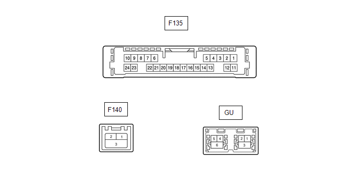
Terminal No. (Symbol) | Wire Color | Terminal Description | Condition | Specified Condition |
|---|---|---|---|---|
F135-6 (VOI+) - F135-23 (GND) |
B - W-B*2 W - W-B*3 |
Voice signal |
Voice guidance output |
The output waveform is synchronized with the output sound |
F135-7 (VOI-) - F135-23 (GND) |
W - W-B*2 B - W-B*3 |
Voice signal |
Voice guidance output |
The output waveform is synchronized with the output sound |
F135-8 (SLD1) - Body ground |
Shield - Body ground |
Shield ground |
Always |
Below 1 Ω |
F135-9 (SPD) - F135-23 (GND) |
V - W-B |
Vehicle speed signal |
See the "Check GPS and Vehicle Sensors" section in Operation Check |
- |
F135-10 (+B) - F135-23 (GND) |
Y - W-B |
Power supply (+B) |
Always |
11 à 14 V |
F135-13 (MIC+) - F135-23 (GND) |
W - W-B |
Microphone voice signal |
See the "Microphone Check (MEU)" section in Operation Check |
- |
F135-14 (MIC-) - Body ground |
B - Body ground |
Microphone voice signal |
See the "Microphone Check (MEU)" section in Operation Check |
- |
F135-19 (REV2) - F135-23 (GND) |
B - W-B*2 G - W-B*3 |
Reverse signal |
The hybrid control system is on: shift the shift lever from any position other than R to R |
2 V max → 11 to 14 V |
F135-21 (SUP) - F135-23 (GND) |
W - W-B*2 R - W-B*3 |
Power supply (ACC) |
20 seconds elapse after the engine switch is set to ON (ACC) |
11 à 14 V |
F135-22 (RST)*1 |
L |
- |
- |
- |
F135-23 (GND) - Body ground |
W-B - Body ground |
Ground |
Engine switch in OFF position |
Below 1 Ω |
F140-1 (USB+) |
- |
USB communication line |
- |
- |
F140-2 (USB-) |
- |
USB communication line |
- |
- |
F140-3 (USBS) - Body ground |
Shield - Body ground |
Shield ground |
Always |
Below 1 Ω |
GU-1 (GVO-) |
- |
Video signal (digital) |
- |
- |
GU-2 (GVO+) |
- |
Video signal (digital) |
- |
- |
GU-3 (GVG1) - Body ground |
Shield - Body ground |
Shield ground |
Always |
Below 1 Ω |
GU-4 (USB+) |
- |
USB communication line |
- |
- |
GU-5 (USB-) |
- |
USB communication line |
- |
- |
GU-6 (USBG) - Body ground |
Shield - Body ground |
Shield ground |
Always |
Below 1 Ω |
- *1: Connected, but not used
- *2: TMMT made
- *3: Manufactured by TMC
DCM (TELEMATICS TRANSCEIVER)
Click here