Telephone Microphone Disconnected (B1579)
DESCRIPTION
The radio and display receiver assembly and the map light assembly (telephone microphone assembly) are connected to each other by microphone connection detection signal lines.
This DTC is stored when a microphone connection detection signal line is disconnected.
DTC No. | Detection Item | DTC Detection Condition | Suspected Area |
|---|---|---|---|
B1579 |
Voice Recognition Microphone Disconnected |
Telephone microphone signal lost. |
|
WIRING DIAGRAM
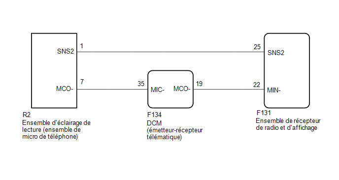
PRECAUTION / NOTICE / HINT
NOTICE:
- When replacing the radio and display receiver assembly or the navigation ECU, always replace it with a new part. If a radio and display receiver assembly or navigation ECU previously installed on another vehicle is reused, the following may occur:
- A communication malfunction DTC is stored.
- The radio and display receiver assembly or navigation ECU may not operate correctly.
- If the DCM (Data Communication Module) has been replaced, perform the activation procedure using the DCM screen (with SOS (manual)).
Click here

PROCEDURE
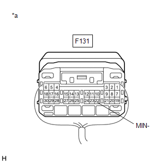
CHECK RADIO AND DISPLAY RECEIVER ASSEMBLY
(a) Measure the resistance according to the value(s) in the table below. Standard resistance:
|
|
| NG |  |
REPLACE RADIO AND DISPLAY RECEIVER ASSEMBLY |
|

CHECK HARNESS AND CONNECTOR (DCM (DATA COMMUNICATION MODULE) - MAP LIGHT ASSEMBLY (TELEPHONE MICROPHONE ASSEMBLY))
(a) Disconnect connector F134 from the DCM (Data Communication Module).
(b) Disconnect connector R2 from the map light assembly (telephone microphone assembly).
(c) Measure the resistance according to the value(s) in the table below.
Standard resistance:
Tester Connection | Condition | Specified Condition |
|---|---|---|
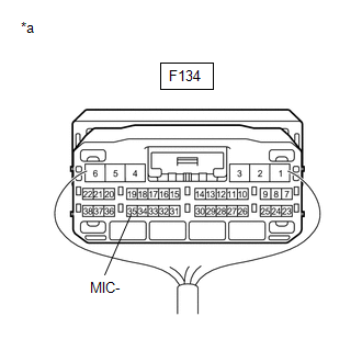
F134-35 (MIC-) - R2-7 (MCO-) |
Always |
Below 1 Ω |
F134-35 (MIC-) - Body ground |
Always |
10 kΩ minimum |
| NG | |
REPAIR OR REPLACE HARNESS OR CONNECTOR |
|
CHECK HARNESS AND CONNECTOR (RADIO RECEIVER AND DISPLAY ASSEMBLY - DCM (TELEMATICS TRANSCEIVER))
(a) Disconnect the F131 connector from the radio and display receiver assembly.
(b) Disconnect the F134 DCM (telematics transceiver) connector.
(c) Measure the resistance according to the value(s) in the table below.
Standard resistance:
Tester Connection | Condition | Specified Condition |
|---|---|---|
F131-22 (MIN-) - F134-19 (MCO-) |
Always |
Below 1 Ω |
F131-22 (MIN-) - Body ground |
Always |
10 kΩ minimum |
| NG | |
REPAIR OR REPLACE HARNESS OR CONNECTOR |
|
CHECK WIRE HARNESS AND CONNECTOR (RADIO AND DISPLAY RECEIVER ASSEMBLY - MAP LIGHT ASSEMBLY (TELEPHONE MICROPHONE ASSEMBLY))
(a) Disconnect the F131 connector from the radio and display receiver assembly.
(b) Disconnect connector R2 from the map light assembly (telephone microphone assembly).
(c) Measure the resistance according to the value(s) in the table below.
Standard resistance:
Tester Connection | Condition | Specified Condition |
|---|---|---|
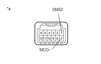
F131-25 (SNS2) - R2-1 (SNS2) |
Always |
Below 1 Ω |
F131-25 (SNS2) - Body ground |
Always |
10 kΩ minimum |
| NG | |
REPAIR OR REPLACE HARNESS OR CONNECTOR |
|
CHECK DCM (TELEMATICS TRANSCEIVER)
(a) Measure the resistance according to the value(s) in the table below. Standard resistance:
|
|
| NG | |
REPLACE DCM (DATA COMMUNICATION MODULE) |
|
CHECK MAP LIGHT ASSEMBLY (TELEPHONE MICROPHONE ASSEMBLY)
(a) Remove the map light assembly (telephone microphone assembly).
Click here
(b) Measure the resistance according to the value(s) in the table below. Standard resistance:
|
|
| OK | |
REPLACE RADIO AND DISPLAY RECEIVER ASSEMBLY |
| NG | |
REPLACE MAP LIGHT ASSEMBLY |