Airbag signal malfunction/no signal transmission (B15C4)
DESCRIPTION
If the DCM (telematics transceiver) detects a communication error between the DCM (telematics transceiver) and the airbag sensor assembly during the DCM self-diagnosis, this DTC will be output.
DTC No. | Detection Item | DTC Detection Condition | Suspected Area |
|---|---|---|---|
B15C4 |
Airbag Signal Malfunction/No Transmission |
The DCM (telematics transceiver) detects an error in the signals transmitted by the airbag sensor assembly when the ignition switch is ON. |
|
WIRING DIAGRAM
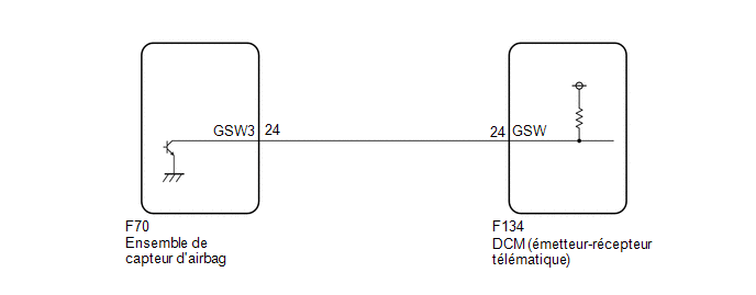
PRECAUTION / NOTICE / HINT
NOTICE:
This vehicle is equipped with an SRS (Supplemental Restraint System) including components such as airbags. Before performing any service (including removal or installation of parts), read the SRS precautions carefully.
Click here
PROCEDURE
INSPECT DTCs (AIRBAG SYSTEM)
(a) Turn the ignition switch OFF.
(b) Connect the Techstream to the DLC3.
(c) Turn the ignition switch to ON and wait for 10 seconds.
(d) Turn on the Techstream.
(e) Clear the DTCs.
Body Electrical > SRS Airbag > Clear DTCs(f) Check the DTCs again.
Body Electrical > SRS Airbag > Trouble CodesResult:
Result | Proceed to |
|---|---|
No DTCs are output |
A |
DTCs are output |
B |
| B |  |
GO TO AIRBAG SYSTEM |
|

INSPECT DCM (TELEMATICS TRANSCEIVER) (GSW SIGNAL)
(a) Remove the DCM (telematics transceiver), but do not disconnect the connectors. Click here |
|
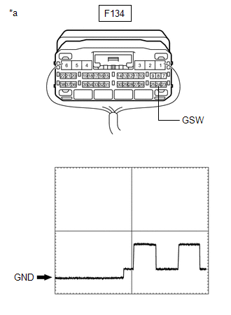
(b) Measure the voltage according to the value(s) in the table below.
Standard voltage:
Tester Connection | Ignition switch position | Specified Condition |
|---|---|---|
F134-24 (GSW) - Body ground |
Ignition Switch in ON position |
6,5 à 8,5 V |
Reference waveform:
Item | Condition |
|---|---|
Tester Connection |
F134-24 (GSW) - Body ground |
Oscilloscope Setting |
5.0 V/DIV., 20 ms/DIV. |
Vehicle Operating Conditions |
Ignition Switch in ON position |
Result:
Result | Proceed to |
|---|---|
8.5 V minimum |
A |
Below 6.5 V |
B |
6,5 à 8,5 V |
C |
| B | |
GO TO STEP 4 |
| C | |
GO TO STEP 5 |
|
INSPECT WIRE HARNESS AND CONNECTOR (CHECK FOR OPEN CIRCUIT)
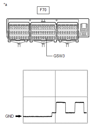
(a) Remove the airbag sensor assembly, but do not disconnect the connectors.
Click here
(b) Measure the voltage according to the value(s) in the table below. Standard voltage:
Reference waveform:
|
|
| OK | |
REPLACE AIRBAG SENSOR ASSEMBLY |
| NG | |
REPAIR OR REPLACE HARNESS OR CONNECTOR |
INSPECT WIRE HARNESS AND CONNECTOR (CHECK FOR SHORT CIRCUIT)
(a) Disconnect connector F134 from the DCM (Data Communication Module).
(b) Measure the resistance according to the value(s) in the table below.
Standard resistance:
Tester Connection | Condition | Specified Condition |
|---|---|---|
F134-24 (GSW) - Body ground |
Always |
10 kΩ minimum |
F70-24 (GSW3) - Body ground |
Always |
10 kΩ minimum |
| NG | |
GO TO STEP 6 |
|
REPLACE DCM (DATA COMMUNICATION MODULE)
(a) Replace the DCM (telematics transceiver).
Click here
NOTICE:
- The ignition switch must be in the OFF position.
- Do not swap the DCM (telematics transceiver) with a DCM from another vehicle.
| NEXT | |
PERFORM DCM ACTIVATION |
INSPECT WIRE HARNESS AND CONNECTOR (DCM (TELEMATICS TRANSCEIVER) - AIRBAG SENSOR ASSEMBLY)
(a) Disconnect connector F134 from the DCM (Data Communication Module).
(b) Disconnect connector F70 from the airbag sensor assembly.
(c) Measure the resistance according to the value(s) in the table below.
Standard resistance:
Tester Connection | Condition | Specified Condition |
|---|---|---|
F134-24 (GSW) - F70-24 (GSW3) |
Always |
Below 1 Ω |
F134-24 (GSW) or F70-24 (GSW3) - Body ground |
Always |
10 kΩ minimum |
| OK | |
REPLACE AIRBAG SENSOR ASSEMBLY |
| NG | |
REPAIR OR REPLACE HARNESS OR CONNECTOR |