Manual switch malfunction (B15C5)
DESCRIPTION
This DTC is output when the DCM (telematics transceiver) detects an open or short circuit in the manual (SOS) switch.
DTC No. | Detection Item | DTC Detection Condition | Suspected Area |
|---|---|---|---|
B15C5 |
Emergency Button Malfunction |
An open or short circuit in the manual (SOS) switch is detected. |
|
WIRING DIAGRAM
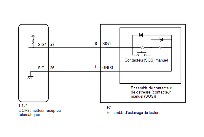
PRECAUTION / NOTICE / HINT
HINT:
Before performing this diagnostic procedure, make sure to perform the status check and make sure that the DCM/VIN registration information is correct.
Click here
PROCEDURE
CHECK DTCs
(a) Turn the ignition switch OFF.
(b) Connect the Techstream to the DLC3.
(c) Turn the ignition switch to ON and wait for 10 seconds.
(d) Turn on the Techstream.
(e) Clear the DTCs.
Body Electrical > Telematics > Clear DTCs(f) Check the DTCs again.
Body Electrical > Telematics > Trouble CodesResult:
Result | Proceed to |
|---|---|
DTCs B1570, B1571 and B15C5 are output |
A |
DTC B15C5 is output (DTCs B1570 and B1571 are not output) |
B |
| B |  |
GO TO STEP 6 |
|

INSPECT MAP LIGHT ASSEMBLY
(a) Disconnect the R4 connector from the reading light assembly. |
|
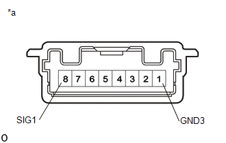
(b) Measure the resistance according to the value(s) in the table below.
Standard resistance:
Tester Connection | Ignition switch position | Specified Condition |
|---|---|---|
8 (SIG1) - 1 (GND3) |
Manual (SOS) switch not pressed |
392 à 432 Ω |
8 (SIG1) - 1 (GND3) |
Manual (SOS) switch pressed |
78 à 86 Ω |
| NG | |
GO TO STEP 5 |
|
CHECK WIRE HARNESS AND CONNECTOR (DCM (TELEMATICS TRANSCEIVER) - READING LIGHT ASSEMBLY)
(a) Disconnect connector F134 from the DCM (Data Communication Module).
(b) Disconnect connector R4 from the map light assembly.
(c) Measure the resistance according to the value(s) in the table below.
Standard resistance:
Tester Connection | Condition | Specified Condition |
|---|---|---|
F134-26 (SIG-) - R4-1 (GND3) |
Always |
Below 1 Ω |
F134-26 (SIG-) or R4-1 (GND3) - Body ground |
Always |
10 kΩ minimum |
F134-27 (SIG1) - R4-8 (SIG1) |
Always |
Below 1 Ω |
F134-27 (SIG1) or R4-8 (SIG1) - Body ground |
Always |
10 kΩ minimum |
| NG | |
REPAIR OR REPLACE HARNESS OR CONNECTOR |
|
REPLACE DCM (DATA COMMUNICATION MODULE)
(a) Replace the DCM (telematics transceiver).
Click here
NOTICE:
- The ignition switch must be in the OFF position.
- Do not swap the DCM (telematics transceiver) with a DCM from another vehicle.
| NEXT | |
PERFORM DCM ACTIVATION |
INSPECT EMERGENCY SWITCH ASSEMBLY (MANUAL (SOS) SWITCH) (RED INDICATOR)
(a) Remove the emergency switch assembly (manual (SOS) switch).
Click here
(b) Inspect the emergency switch assembly (manual (SOS) switch).
Click here
| OK | |
REPLACE MAP LIGHT ASSEMBLY |
| NG | |
REPLACE EMERGENCY SWITCH ASSEMBLY (MANUAL (SOS) SWITCH) |
READ VALUE USING TECHSTREAM (MANUAL (SOS) SWITCH OPERATION)
(a) Turn the ignition switch OFF.
(b) Connect the Techstream to the DLC3.
(c) Turn the ignition switch to ON and wait for 10 seconds.
(d) Turn on the Techstream.
(e) Select the following menu items: Body Electrical / Telematics / Data List.
(f) Check that the manual (SOS) switch position shown on the Techstream changes according to the operation of the manual (SOS) switch.
Body Electrical > Telematics > Data ListTester display | Item | Range | Normal Condition | Diagnostic Note |
|---|---|---|---|---|
Emergency Switch |
Manual (SOS) Switch |
OFF or ON |
OFF: Manual (SOS) switch not pressed ON: Manual (SOS) switch pressed* |
- |
Emergency Switch
- *: Pressing the manual (SOS) switch connects to the call center.
Result:
Result | Proceed to |
|---|---|
The Techstream display changes when the manual (SOS) switch is set to ON/OFF |
A |
The Techstream display does not change when the manual (SOS) switch is set to ON/OFF |
B |
| B | |
GO TO STEP 8 |
|
REPLACE DCM (DATA COMMUNICATION MODULE)
(a) Replace the DCM (telematics transceiver).
Click here
NOTICE:
- The ignition switch must be in the OFF position.
- Do not swap the DCM (telematics transceiver) with a DCM from another vehicle.
| NEXT | |
PERFORM DCM ACTIVATION |
INSPECT DCM (TELEMATICS TRANSCEIVER) (SIG1 VOLTAGE)
(a) Remove the DCM (telematics transceiver), but do not disconnect the connectors. Click here |
|
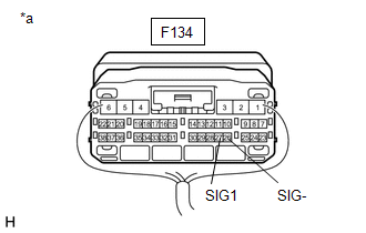
(b) Measure the voltage according to the value(s) in the table below.
Standard voltage:
Tester Connection | Ignition switch position | Specified Condition |
|---|---|---|
F134-27 (SIG1) - F134-26 (SIG-) |
Ignition switch ON, manual (SOS) switch not pressed |
1,5 à 2,0 V |
| NG | |
GO TO STEP 10 |
|
REPLACE DCM (DATA COMMUNICATION MODULE)
(a) Replace the DCM (telematics transceiver).
Click here
NOTICE:
- The ignition switch must be in the OFF position.
- Do not swap the DCM (telematics transceiver) with a DCM from another vehicle.
| NEXT | |
PERFORM DCM ACTIVATION |
INSPECT MAP LIGHT ASSEMBLY
(a) Disconnect the R4 connector from the reading light assembly. |
|
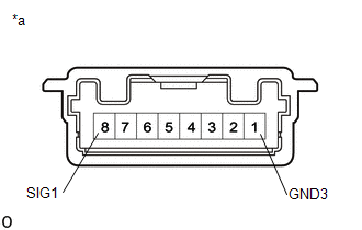
(b) Measure the resistance according to the value(s) in the table below.
Standard resistance:
Tester Connection | Condition | Specified Condition |
|---|---|---|
8 (SIG1) - 1 (GND3) |
Manual (SOS) switch not pressed |
392 à 432 Ω |
8 (SIG1) - 1 (GND3) |
Manual (SOS) switch pressed |
78 à 86 Ω |
| NG | |
GO TO STEP 13 |
|
INSPECT WIRE HARNESS AND CONNECTOR (TELEMATICS TRANSCEIVER (DCM) - EMERGENCY SWITCH ASSEMBLY (SOS (MANUAL) SWITCH))
(a) Disconnect connector F134 from the DCM (Data Communication Module).
(b) Disconnect connector R4 from the map light assembly.
(c) Measure the resistance according to the value(s) in the table below.
Standard resistance:
Tester Connection | Condition | Specified Condition |
|---|---|---|
F134-27 (SIG1) - R4-8 (SIG1) |
Always |
Below 1 Ω |
F134-27 (SIG1) or R4-8 (SIG1) - Body ground |
Always |
10 kΩ minimum |
| NG | |
REPAIR OR REPLACE HARNESS OR CONNECTOR |
|
REPLACE DCM (DATA COMMUNICATION MODULE)
(a) Replace the DCM (telematics transceiver).
Click here
NOTICE:
- The ignition switch must be in the OFF position.
- Do not swap the DCM (telematics transceiver) with a DCM from another vehicle.
| NEXT | |
PERFORM DCM ACTIVATION |
INSPECT EMERGENCY SWITCH ASSEMBLY (MANUAL (SOS) SWITCH) (RED INDICATOR)
(a) Remove the emergency switch assembly (manual (SOS) switch).
Click here
(b) Inspect the emergency switch assembly (manual (SOS) switch).
Click here
| OK | |
REPLACE MAP LIGHT ASSEMBLY |
| NG | |
REPLACE EMERGENCY SWITCH ASSEMBLY (MANUAL (SOS) SWITCH) |