Central Locking - General Information and Operational Check
Models without remote control
The system operates by actuating the individual lock actuators of each vehicle door. The system consists of control switches, door actuators and connecting wiring. Diagnosis of lock faults is limited to checking the condition of the electrical circuit contact connections and the operation of the door actuators.
The central locking operates by means of bidirectional solenoids located in the vehicle doors. The control switch has two positions: LOCK and UNLOCK. On later models equipped with a remote control, the door actuators also feature a control module that supplies voltage to the lock actuators on command from the remote control. When activated, the switch sends a ground signal to the door lock control module, which results in the corresponding switching of the actuators. Depending on the initial position of the switch, the control module simply reverses the polarity of the current supplied to the solenoids when the switch is operated. On models without remote control, the switches act on the actuators directly.
If the cause of the system malfunction cannot be found during the checks listed below, drive the vehicle to a service station for more complete diagnosis.
Always check the circuit protection first. On these models, circuit protection is provided by fuses 6 and 13 in the junction block located on the right under the instrument panel, and fuse 9 in the left junction block.
Operate the control switches in both directions with the engine off. Listen for the clicks produced by the relay operation.
If there are no clicks, check that voltage is supplied to the switches. If there is no voltage, check the condition of the wiring between the junction block and the corresponding switch.
If voltage is present but no click is heard, check the continuity of the switch in both positions. Replace defective switches.
If the switch is good, check the continuity of the wiring between the switch and the solenoid of the corresponding actuator. Repair any damaged wiring.
If only one of the actuators is faulty, remove the interior door trim panel from the corresponding door (see Body section) and check that voltage is supplied to the actuator solenoid while operating the control switch. One wire should be energized in one switch position, and the second wire in the other.
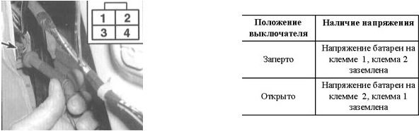
If voltage supply is correct, replace the solenoid.
Wire breaks most often occur in the section between the door and the body panel.
Models with remote control
On these models, the remote control transmits a long-wave infrared signal, which is received and decoded by the system control module. On receiving the signal from the remote control, the module issues a command to actuate the door lock actuators.
Replace the remote control batteries when the indicator LED built into the remote control housing stops lighting when the control button is pressed.
Separate the remote control housing into two halves by prying with a small screwdriver.
Use a CR 2025 lithium battery as the replacement.
Make sure the housing latches engage securely.
Test yourself
A quick Honda Accord quiz: every answer comes with an explanation and a link to the manual page.