Ignition Signal
INSPECTION START
Turn ignition switch OFF, and restart engine.
Does the engine start?
YES>>With CONSULT: GO TO 2.
YES>>Without CONSULT: GO TO 3.
NO>>Proceed to Diagnosis Procedure.
CHECK IGNITION SIGNAL FUNCTION
 With CONSULT
Perform “POWER BALANCE” in “ACTIVE TEST” mode with CONSULT.
Check that each circuit produces a momentary engine speed drop.
Is the inspection result normal?
YES>>INSPECTION END
NO>>Proceed to Diagnosis Procedure.
CHECK IGNITION SIGNAL FUNCTION
 Without CONSULT
Let engine idle.
Read the voltage signal between ECM harness connector terminals with an oscilloscope.
ECM Voltage signal + – Connector Terminal Connector Terminal F79 103 E32 152 
104 106 107 113 114
Is the inspection result normal?
YES>>INSPECTION END
NO>>Proceed to Diagnosis Procedure.
CHECK ECM POWER SUPPLY
Turn ignition switch OFF, wait at least 10 seconds and then turn it ON.
Check the voltage between ECM harness connector terminals.
ECM Voltage Connector Terminal Connector Terminal F79 86 E32 152 Battery voltage
Is the inspection result normal?
YES>>GO TO 2.
NO>>Refer to Diagnosis Procedure.
CHECK CONDENSER-1 POWER SUPPLY
Turn ignition switch OFF.
Disconnect condenser-1 harness connector.
Turn ignition switch ON.
Check the voltage between condenser-1 harness connector and ground.
Condenser-1 Ground Voltage Connector Terminal F26 1 Ground Battery voltage
Is the inspection result normal?
YES>>GO TO 4.
NO>>GO TO 3.
CHECK CONDENSER-1 POWER SUPPLY CIRCUIT
Turn ignition switch OFF.
Disconnect IPDM E/R harness connector.
Check the continuity between IPDM E/R harness connector and condenser-1 harness connector.
IPDM E/R Condenser-1 Continuity Connector Terminal Connector Terminal F19 55 F26 1 Existed Also check harness for short to ground and short to power.
Is the inspection result normal?
YES>>Refer to Diagnosis Procedure.
NO>>Repair open circuit, short to ground or short to power in harness or connectors.
CHECK CONDENSER-1 GROUND CIRCUIT
Turn ignition switch OFF.
Check the continuity between condenser-1 harness connector and ground.
Condenser-1 Ground Continuity Connector Terminal F26 2 Ground Existed Also check harness for short to power.
Is the inspection result normal?
YES>>GO TO 5.
NO>>Repair open circuit or short to power in harness or connectors.
CHECK CONDENSER-1
Check condenser-1. Refer to Component Inspection (Condenser-1)
Is the inspection result normal?
YES>>GO TO 6.
NO>>Replace condenser-1.
CHECK IGNITION COIL POWER SUPPLY
Reconnect all harness connectors disconnected.
Disconnect ignition coil harness connector-1.
Turn ignition switch ON.
Check the voltage between ignition coil harness connector and ground.
Ignition coil Ground Voltage Cylinder Connector Terminal 1 F47 3 Ground Battery voltage 2 F8 3 3 F48 3 4 F9 3 5 F49 3 6 F10 3
Is the inspection result normal?
YES>>GO TO 7.
NO>>Repair or replace harness or connectors.
CHECK IGNITION COIL GROUND CIRCUIT FOR OPEN AND SHORT
Turn ignition switch OFF.
Check the continuity between ignition coil harness connector and ground.
Ignition coil Ground Continuity Cylinder Connector Terminal 1 F47 2 Ground Existed 2 F8 2 3 F48 2 4 F9 2 5 F49 2 6 F10 2 Also check harness for short to power.
Is the inspection result normal?
YES>>GO TO 8.
NO>>Repair open circuit or short to power in harness or connectors.
CHECK IGNITION COIL OUTPUT SIGNAL CIRCUIT FOR OPEN AND SHORT
Disconnect ECM harness connector.
Check the continuity between ignition coil harness connector and ECM harness connector.
Ignition coil ECM Continuity Cylinder Connector Terminal Connector Terminal 1 F47 1 F79 113 Existed 2 F8 1 106 3 F48 1 103 4 F9 1 114 5 F49 1 107 6 F10 1 104 Also check harness for short to ground and short to power.
Is the inspection result normal?
YES>>GO TO 9.
NO>>Repair open circuit, short to ground or short to power in harness or connectors.
CHECK IGNITION COIL WITH POWER TRANSISTOR
Check ignition coil with power transistor. Refer to Component Inspection (Ignition Coil with Power Transistor).
Is the inspection result normal?
YES>>Check intermittent incident. Refer to Intermittent Incident.
NO>>Replace malfunctioning ignition coil with power transistor. Refer to Removal and Installation (bank 2), Removal and Installation (bank 1).
CHECK IGNITION COIL WITH POWER TRANSISTOR-I
Turn ignition switch OFF.
Disconnect ignition coil harness connector.
Check resistance between ignition coil terminals as per the following.
Terminal No. (Polarity) Resistance Ω [at 25 °C] 1 and 2 Except 0 or ∞ 1 and 3 Except 0 2 and 3
Is the inspection result normal?
YES>>GO TO 2.
NO>>Replace malfunctioning ignition coil with power transistor. Refer to Removal and Installation (bank 2), Removal and Installation (bank 1).
CHECK IGNITION COIL WITH POWER TRANSISTOR-II
Turn ignition switch OFF.
Reconnect all harness connectors disconnected.
Remove fuel pump fuse in IPDM E/R to release fuel pressure.
Start engine.
After engine stalls, crank it 2 or 3 times to release all fuel pressure.
Turn ignition switch OFF.
Remove all ignition coil harness connectors to avoid the electrical discharge from the ignition coils.
Remove ignition coil and spark plug of the cylinder to be checked.
Crank engine for 5 seconds or more to remove combustion gas in the cylinder.
Connect spark plug and harness connector to ignition coil.
Fix ignition coil using a rope etc. with gap of 13 - 17 mm (0.52 - 0.66 in) between the edge of the spark plug and grounded metal portion as shown in the figure.
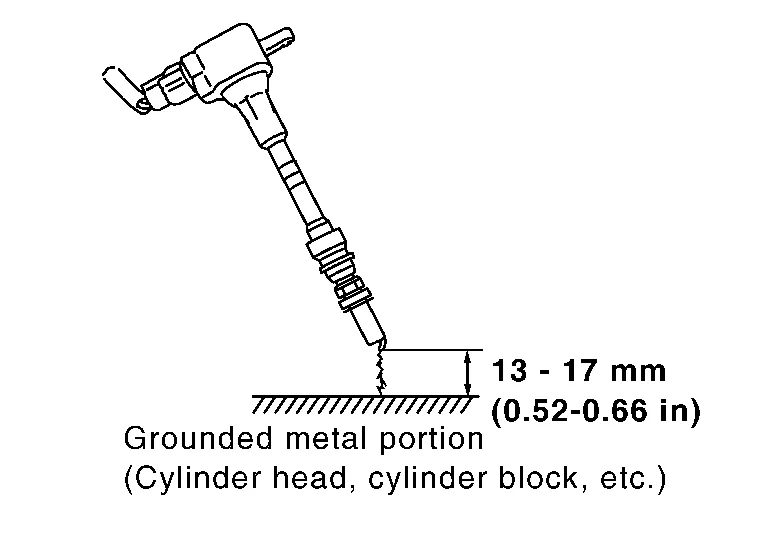
Crank engine for approximately 3 seconds, and check whether spark is generated between the spark plug and the grounded metal portion.
Spark should be generated.
Is the inspection result normal?
YES>>INSPECTION END
NO>>Replace malfunctioning ignition coil with power transistor. Refer to Removal and Installation (bank 2), Removal and Installation (bank 1).
CHECK CONDENSER-1
Turn ignition switch OFF.
Disconnect condenser-1 harness connector.
Check resistance between condenser-1 terminals as per the following.
Terminals Resistance 1 and 2 Above 1 MΩ [at 25C° (77C°)]
Is the inspection result normal?
YES>>INSPECTION END
NO>>Replace condenser-1.