Checking Control Unit (Transistor Ignition System)
PROCEDURE
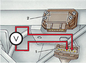
Checking Voltage at Control Unit Terminals 2 and 4 1 – connector block; 2 – control unit
To check the control unit when the ignition coil is serviceable, proceed as follows. PROCEDURE 1. Disconnect connector 1 from the control unit. Turn on the ignition and measure the voltage between terminals 2 and 4 of the connector, as shown in the illustration. The voltage should be approximately 12 V (battery voltage). If the voltage differs from the specified value, locate and repair the open circuit in the wiring. 2. Turn off the ignition and connect connector 1 to the control unit. 3. Disconnect connector 18 (see Fig. Transistorized Ignition System) from the distributor. 4. Connect a voltmeter to terminals 6 and 4 of the ignition coil. Turn on the ignition and measure the voltage. It should be at least 2 V and drop to zero within 1–2 s. If this does not occur, replace the control unit and the ignition coil. 5. Connect the center terminal of connector 18 to ground with a wire. The voltage should increase to 2 V. Otherwise, replace the control unit. 6. Turn off the ignition. Connect the voltmeter to the outer terminals of connector 18. Turn on the ignition and measure the voltage. It should be 5 V. If not, check the wiring.
Test yourself
A quick Volkswagen Golf quiz: every answer comes with an explanation and a link to the manual page.