Instrument cluster
PROCEDURE
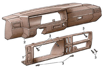
Instrument Panel Components 1 – instrument cluster trim; 2 – instrument panel; 3 – screw
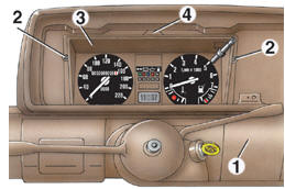
Instrument Cluster Mounting 1 – instrument panel; 2 – screw; 3 – instrument cluster; 4 – lug
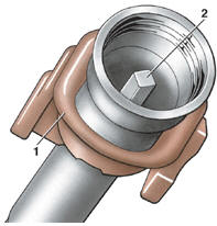
Speedometer Cable 1 – speedometer cable; 2 – cable retaining clip
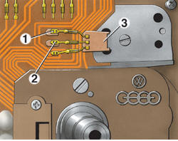
Voltage Stabilizer 1 – positive terminal; 2 – negative terminal; 3 – voltage stabilizer

LED Installation 1 – negative terminal; 2 – LED

Speedometer Mounting

Tachometer Mounting 1 – coolant temperature gauge mounting screw; 2 – fuel level gauge mounting screw; 3 – tachometer mounting screw; 4 – spring clip
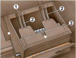
Connector Housing 1 – bar; 2 – lug; 3 – housing
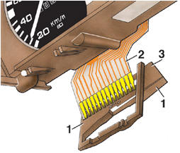
Connector Housing Removal 1 – latch; 2 – flexible strip; 3 – connector housing
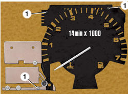
VDO Multifunction Gauge 1 – gauge mounting
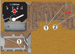
Motometer Multifunction Gauge 1 – gauge mounting; 2 – latch
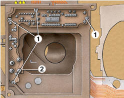
Oil Pressure Control Circuit Board 1 – latch; 2 – circuit board

Clock Connection 1 – negative busbar; 2 – clamp
Removal PROCEDURE 1. Disconnect wire from negative terminal of battery. 2. Remove screws 2 (refer to illustration Upper Shelf Mounting) securing left shelf under instrument panel and remove shelf 1 downward and to the left. 3. Remove all switches from trim 1 (refer to illustration Instrument Panel Components) of instrument cluster. To do this, insert thin screwdriver into gap between trim and switch, from below switch. Turn switch upward with screwdriver and remove it from socket.
4. Disconnect connector with wires from switch. Each connector can only be installed on one switch, so connectors cannot be mixed up when installing switches. 5. Remove knob 1 (refer to illustration Heater Control Mechanism) with washer 2. 6. Pull out knobs 12. 7. Remove panel 3. 8. Remove screws 4 securing bracket 5 of levers, pull bracket 5 forward and disconnect cables 6, 7 and 8 from it. 9. Remove radio. If vehicle has no radio, remove plug from trim 1 (refer to illustration Instrument Panel Components) of instrument cluster. 10. Remove screws 3 and remove instrument cluster trim 1. 11. Remove screws 2 (refer to illustration Instrument Cluster Mounting) and tilt cluster 3 to disengage lug 4 of cluster.
Pull cluster 3 slightly forward. 12. Disconnect speedometer cable from instrument cluster by compressing retaining clip 2 (refer to illustration Speedometer Cable). 13. Disconnect vacuum hose from economy meter (if equipped). 14. Disconnect two 14-pin connectors. To do this, insert screwdriver between connector and socket and carefully pull connector from socket so that spring latch disengages, then remove connector from socket. 15. Remove instrument cluster. VOLTAGE STABILIZER Inspection The stabilizer maintains constant voltage in the instrument cluster.
PROCEDURE 1. Before testing, disconnect the speedometer cable and the vacuum hose from the economy meter. 2. All electrical connectors must be connected to the instrument cluster. Do not disconnect the wire from the negative battery terminal. 3. Connect a voltmeter to terminals 1 and 2 (see Fig. Voltage Stabilizer) and turn the ignition on. The stabilizer voltage must be 10 V. If it is above 10.5 V or below 9.5 V, the stabilizer is faulty and must be replaced. LIGHT EMITTING DIODES Installation PROCEDURE When installing the light emitting diodes 2 (see Fig. LED Installation), observe the polarity. To reduce the risk of error, bend the negative terminal 1 of the diode to the side. SPEEDOMETER PROCEDURE To remove the speedometer, remove the screws marked with arrows in Fig. Speedometer Mounting. TACHOMETER AND FUEL AND COOLANT TEMPERATURE GAUGES PROCEDURE To remove the coolant temperature gauge, remove screws 1 (see Fig. Tachometer Mounting). To remove the fuel gauge, remove screw 2 and pull the gauge down. To remove the tachometer, remove screws 3. CONNECTOR HOUSING PROCEDURE 1. To remove the connector housing, pry the bar 1 (see Fig. Connector Housing) of the housing with a screwdriver so that it disengages from the projections 2 of the instrument cluster housing, and slide housing 3 in the direction of the arrow. 2. Through the openings in housing 3, release the plastic latches 1 (see Fig. Connector Housing Removal) and remove the flexible connecting bus 2 from housing 3. MULTIFUNCTION GAUGE PROCEDURE 1. To remove the multifunction gauge, remove screws 1 (see Fig. VDO Multifunction Gauge or Fig. Motometr Multifunction Gauge). 2. On the Motometr gauge, press latch 2 in the direction indicated by the arrow. OIL PRESSURE CONTROL PRINTED CIRCUIT BOARD1 PROCEDURE To remove the oil pressure control board 2 (see Fig. Oil Pressure Control Printed Circuit Board), release latches 1. CONNECTING THE CONNECTING BUSES TO THE CLOCK Depending on the equipment, a clock may be installed instead of the tachometer in the instrument cluster. In this case, two flexible buses are connected to it. PROCEDURE Bus 1 (see Fig. Clock Connection) is connected to ground by inserting it under the screw head and clamping it with the screw. The positive bus is put on the clock terminal and secured with plastic clip 2.
Test yourself
A quick Volkswagen Golf quiz: every answer comes with an explanation and a link to the manual page.