Low Beam Indicator Circuit
DESCRIPTION
The main body ECU (multiplex network body ECU) controls the low beams.
WIRING DIAGRAM
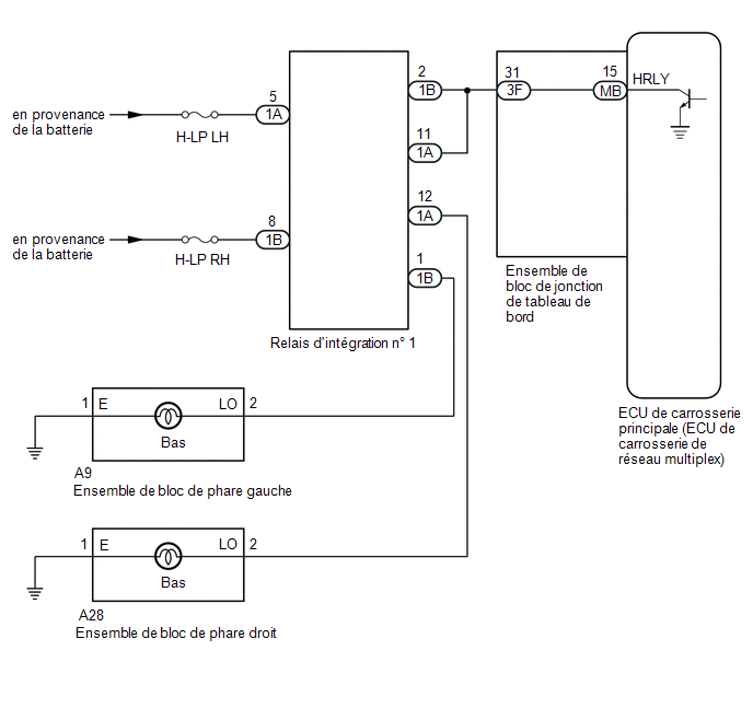
PRECAUTION / NOTICE / HINT
NOTICE:
- Check the fuses and bulbs for the circuits related to this system before performing the following procedure.
- Before replacing the main body ECU (multiplex network body ECU), refer to the registration section.*1
Click here

- *1: with Smart Key System
PROCEDURE
PERFORM ACTIVE TEST USING TECHSTREAM (HEADLIGHT RELAY)
(a) Connect the Techstream to the DLC3.
(b) Turn the ignition switch to ON.
(c) Turn on the Techstream.
(d) Select the following menu items: Body Electrical / Main Body / Active Test.
(e) Check that the relay operates.
Body Electrical > Main Body > Active TestTester display | Item | Control Range | Diagnostic Note |
|---|---|---|---|
Headlight Relay |
Low beam headlights |
ON or OFF |
- |
Headlight Relay
OK:
The headlight relay operates (low beam headlights come on).
| OK |  |
GO TO APPLICABLE SYSTEM AS INDICATED IN THE PROBLEM SYMPTOMS TABLE |
|

CHECK INTEGRATION RELAY NO. 1 (LH HEADLIGHT RELAY, RH HEADLIGHT RELAY)
(a) Remove integration relay No. 1 from the No. 1 engine room relay block.
Click here
(b) Inspect integration relay No. 1.
Click here
OK:
Integration relay No. 1 operates normally.
| NG | |
REPLACE INTEGRATION RELAY NO. 1 |
|
CHECK HARNESS AND CONNECTOR (INTEGRATION RELAY NO. 1 - BATTERY)
(a) Measure the voltage according to the value(s) shown in the table below.
Standard voltage:
Tester Connection | Condition | Specified Condition |
|---|---|---|
1A-5 - Body ground |
Always |
11 à 14 V |
1B-8 - Body ground |
Always |
11 à 14 V |
| NG | |
REPAIR OR REPLACE HARNESS OR CONNECTOR |
|
CHECK HARNESS AND CONNECTOR (INTEGRATION RELAY NO. 1 - LH HEADLIGHT ASSEMBLY AND RH HEADLIGHT ASSEMBLY AND BODY GROUND)
(a) Disconnect connector A9 from the LH headlight assembly.
(b) Disconnect connector A28 from the RH headlight assembly.
(c) Measure the resistance according to the value(s) in the table below.
Standard resistance:
Tester Connection | Condition | Specified Condition |
|---|---|---|
1B-1 - A9-2 (LO) |
Always |
Below 1 Ω |
1A-12 - A28-2 (LO) |
Always |
Below 1 Ω |
A9-1 (E) - Body ground |
Always |
Below 1 Ω |
A28-1 (E) - Body ground |
Always |
Below 1 Ω |
1B-1 - Body ground |
Always |
10 kΩ minimum |
1A-12 - Body ground |
Always |
10 kΩ minimum |
| NG | |
REPAIR OR REPLACE HARNESS OR CONNECTOR |
|
INSPECT WIRE HARNESS AND CONNECTOR (INTEGRATION RELAY NO. 1 - INSTRUMENT PANEL JUNCTION BLOCK ASSEMBLY)
(a) Disconnect the 3F connector from the instrument panel junction block assembly.
(b) Measure the resistance according to the value(s) in the table below.
Standard resistance:
Tester Connection | Condition | Specified Condition |
|---|---|---|
1A-11 - 3F-31 |
Always |
Below 1 Ω |
1B-2 - 3F-31 |
Always |
Below 1 Ω |
1A-11 or 3F-31 - Body ground |
Always |
10 kΩ minimum |
1B-2 or 3F-31 - Body ground |
Always |
10 kΩ minimum |
| NG | |
REPAIR OR REPLACE HARNESS OR CONNECTOR |
|
INSPECT INSTRUMENT PANEL JUNCTION BLOCK ASSEMBLY
(a) Remove the instrument panel junction block assembly.
Click here
(b) Remove the main body ECU (multiplex network body ECU) from the instrument panel junction block assembly.
(c) Measure the resistance according to the value(s) in the table below.
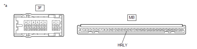
*a |
Component without wire harness connected (instrument panel junction block assembly) |
- |
- |
Standard resistance:
Tester Connection | Condition | Specified Condition |
|---|---|---|
3F-31 - MB-15 (HRLY) |
Always |
Below 1 Ω |
| OK | |
REPLACE MAIN BODY ECU (MULTIPLEX NETWORK BODY ECU) |
| NG | |
REPLACE INSTRUMENT PANEL JUNCTION BLOCK ASSEMBLY |