Open in IG circuit (B242E)
DESCRIPTION
This DTC is stored when a malfunction occurs in the ignition power supply circuit of the left headlight ECU subassembly. The left headlight ECU subassembly stores DTC B242E.
DTC No. | Detection Item | DTC Detection Condition | Suspected Area | Note |
|---|---|---|---|---|
B242E |
IG circuit open |
Open in ignition power supply circuit of left headlight ECU subassembly |
|
- |
WIRING DIAGRAM
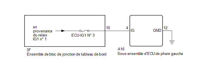
PRECAUTION / NOTICE / HINT
NOTICE:
- Check the fuses for the circuits related to this system before performing the following procedure.
- If the left headlight ECU subassembly has been replaced, it is necessary to synchronize the vehicle information and reset the left headlight ECU subassembly.
Click here

PROCEDURE
CLEAR DTCs
(a) Clear the DTCs.
Click here
|

CHECK WHETHER DTCs ARE OUTPUT
(a) Turn the ignition switch to ON.
(b) Check DTCs.
Click here
OK:
DTC B242E is not output.
| OK |  |
USE SIMULATION METHOD TO CHECK |
|
CHECK WIRE HARNESS AND CONNECTOR (LEFT HEADLIGHT ECU SUBASSEMBLY - POWER SOURCE AND BODY GROUND)
(a) Disconnect the A16 connector from the LH headlight ECU sub-assembly.
(b) Measure the voltage according to the value(s) in the table below.
Standard voltage:
Tester Connection | Ignition switch position | Specified Condition |
|---|---|---|
A16-4 (IG) - Body ground |
Ignition Switch in OFF position |
Below 1 V |
A16-4 (IG) - Body ground |
Ignition Switch in ON position |
11 à 14 V |
(c) Measure the resistance according to the value(s) in the table below.
Standard resistance:
Tester Connection | Condition | Specified Condition |
|---|---|---|
A16-12 (GND) - Body ground |
Always |
Below 1 Ω |
| OK | |
REPLACE LEFT HEADLIGHT ECU SUBASSEMBLY |
| NG | |
REPAIR OR REPLACE HARNESS OR CONNECTOR |